

Content last revised on October 10, 2026
High-Voltage Striking Potential and Secondary Coil Insulation Testing
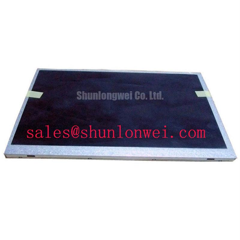
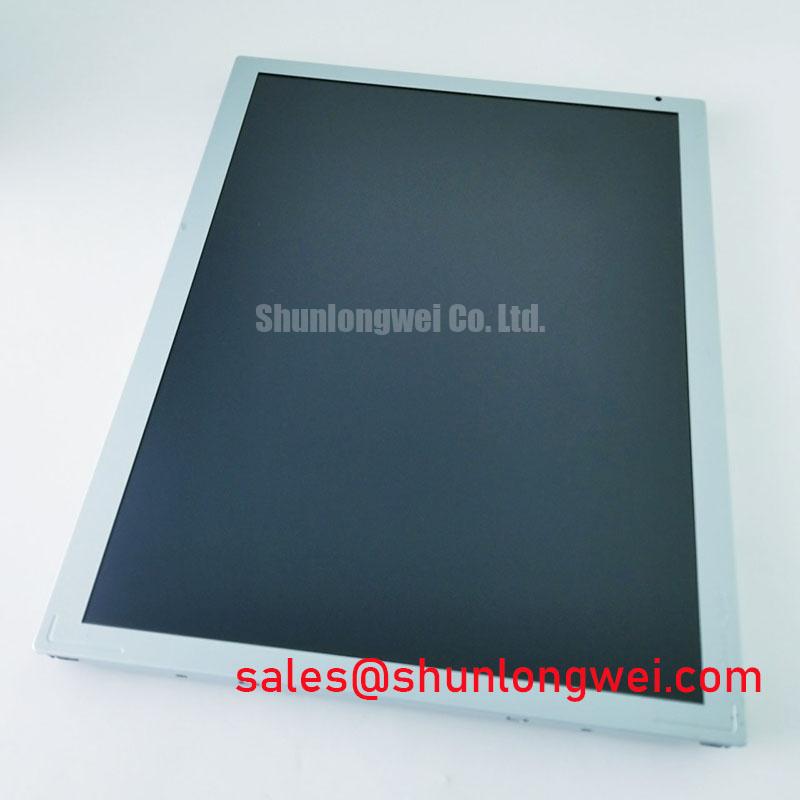
Before applying power to a replacement panel, I isolate the display from the host inverter and inspect the backlight connector, flexible cable seating, and secondary-side insulation path. The supplied baseline identifies the LC150X01-SL02 as a TFT-LCD active matrix color display module, but it does not establish a CCFL ignition rating, LED driver specification, or a factory-approved backlight architecture.
A proposed 1500–1650 Vrms cold-ignition test therefore belongs only to a verified CCFL assembly and must not be treated as an electrical rating of the panel itself. If the original equipment uses a high-voltage CCFL inverter, the service check should focus on insulation clearance, connector contamination, transformer noise, and leakage toward the metal chassis. Acoustic buzzing can also originate from the inverter, mounting structure, or switching waveform rather than from the LCD cell.
When the host system uses a constant-current LED driver, the correct procedure changes. Confirm the driver output range, current control method, dimming interface, and enable sequence from the original equipment documentation before connecting the panel. A claimed 1000:1 PWM dimming capability and a specific LED half-life cannot be assigned to this model without a supporting panel datasheet or backlight document.
For high-EMI equipment such as an AGV or forklift telematics display, route the video interface away from inverter and motor cables, maintain a continuous reference plane where the host board permits, and inspect the connector shield termination. A 100 Ω ± 10% differential target may be appropriate for a particular host interface, but it is a system routing consideration rather than a confirmed LC150X01-SL02 specification. Use the known-good signal path as the comparison reference when checking ringing, common-mode noise, or unequal edge arrival.
For broader panel selection and interface background, the industrial TFT-LCD technology guide provides useful repair-oriented context. The general TFT operating principle is also described by Wikipedia’s TFT-LCD reference.
Logic Supply Voltage Sequencing and Driver IC Latch-Up Risk
Check the host power sequence at the panel connector rather than assuming that a familiar industrial logic voltage is acceptable. The supplied product data does not confirm whether this assembly requires 3.3 V, 5.0 V, or another panel-specific supply arrangement. The system integrator should verify the required voltage, enable signals, ground allocation, and timing from the original panel documentation before energizing the replacement.
On the bench, monitor logic power, display enable, reset behavior, and video activity together. A panel that shows a white field, split image, intermittent image, or unstable startup may be affected by power sequencing, incorrect data mapping, connector contact resistance, or a host timing mismatch. These symptoms should be compared with a known-good unit rather than assigned to a single failed circuit.
JEIDA and VESA mapping are not interchangeable assumptions. Confirm the actual color-bit order, differential pair assignment, clock polarity, and host timing before changing firmware or rewiring the cable. Where the host requires controlled differential routing, maintain the intended impedance through the connector transition and avoid unnecessary stubs. The same principle applies to skew: balance the paired conductors and validate the received waveform at the panel interface.
During incoming inspection, display a full red, green, blue, white, and black sequence. This exposes dead pixels, stuck pixels, uneven illumination, and intermittent FPC contact more reliably than a single desktop image. Bench Tip: Use ESD protection and keep the FPC perfectly level while closing its connector lock; an angled insertion can create intermittent data faults without visible damage.
For an AGV or forklift display, the enclosure, cable length, vibration profile, and controller board determine the practical signal margin. Designers should verify the complete assembly under the intended motor switching environment instead of treating the panel model alone as an EMC-certified subsystem. A same-size reference option, LM150X08-TL02, can be reviewed separately for mechanical and interface comparison, not as an automatic replacement.
Preventing Localized Light Guide Plate Compression on Dark Fields
Dark-field inspection should be performed after the panel has reached stable operating temperature, with the display viewed straight-on and then from practical operator angles. Look for corner shadows, pressure marks, bright edge bands, and localized mura that follows the bezel or fastening points. These patterns can result from enclosure compression, uneven support, cable tension, or a panel assembly that does not match the original mechanical envelope.
The supplied baseline does not confirm the internal light-guide material, optical stack, bezel dimensions, or factory fastener torque for the LC150X01-SL02. Do not transfer a cross-pattern fastening value such as 0.35–0.45 N·m to this model as an official limit. The chassis designer should use the original mechanical drawing, distribute clamping force evenly, and prevent the bezel from pressing directly into active optical areas.
FPC routing deserves the same attention as the front bezel. Leave the cable in its natural exit direction, avoid a sharp fold at the connector, and provide strain relief on the host side rather than loading the panel socket. In a vibrating vehicle terminal, the display frame and controller should be supported as a coordinated assembly so that shock loads are not concentrated at the FPC lock.
Cold-start evaluation is best performed by recording the image response, contrast recovery, and touch or keypad feedback at the actual equipment temperature. Liquid-crystal response can change in sub-zero conditions, but no specific −20 °C to −30 °C operating range or heater-strip provision is established by the supplied product information. If the enclosure includes environmental heating, its control strategy must be validated at system level without allowing local thermal gradients to distort the display.
Constant Luminance Control and L70/B50 Reliability Verification
Uniform luminance testing begins with a calibrated white field, followed by gray and black screens that reveal edge falloff, optical mura, and localized thermal effects. Record the result with consistent camera exposure and panel warm-up conditions; a visual comparison made at different brightness settings can misrepresent a genuine change in uniformity.
The LC150X01-SL02 baseline confirms the product category and construction class, but it does not provide an official LED L70/B50 curve, 50,000-hour half-brightness claim, thermal resistance value, or aluminum heat-spreader requirement. Those figures must not be presented as guaranteed life data for this model. If a narrow display edge becomes visibly brighter or darker during operation, inspect the backlight driver current, enclosure heat paths, connector seating, and local mechanical pressure before changing the panel.
Where the host uses differential video, keep the pair geometry consistent through the board connector and cable transition. A nominal 100 Ω differential routing target may be used when required by the host interface design, while pair-to-pair timing balance should be checked with the actual cable and connector installed. Validate the display under motor starts, braking events, and radio activity when the panel is integrated into mobile industrial equipment.
Long static HMI screens also deserve an operational review. Use suitable screen refresh practices, rotate fixed diagnostic pages where the application allows, and verify any image-retention behavior against the actual panel documentation. For optical and industrial display technology context, the Winstar industrial TFT-LCD and OLED reference offers a useful comparison of display-module terminology and integration considerations.