


Content last revised on September 10, 2026
Mechanical Stress and Glass-Substrate Fracture Prevention
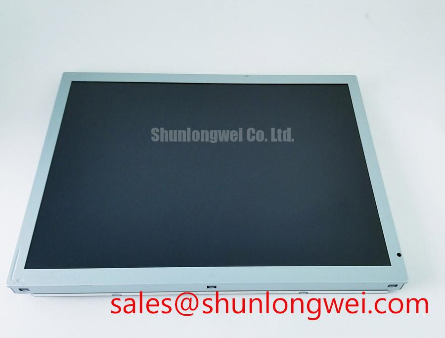
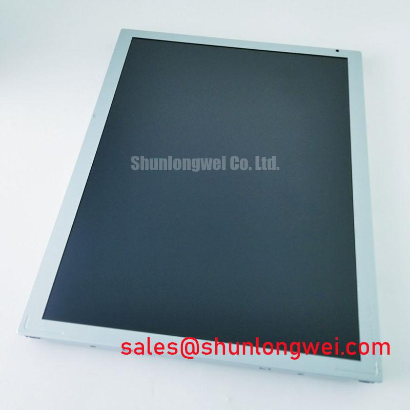
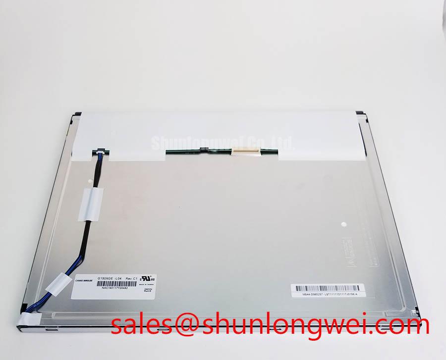
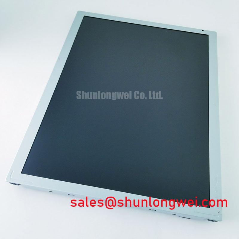
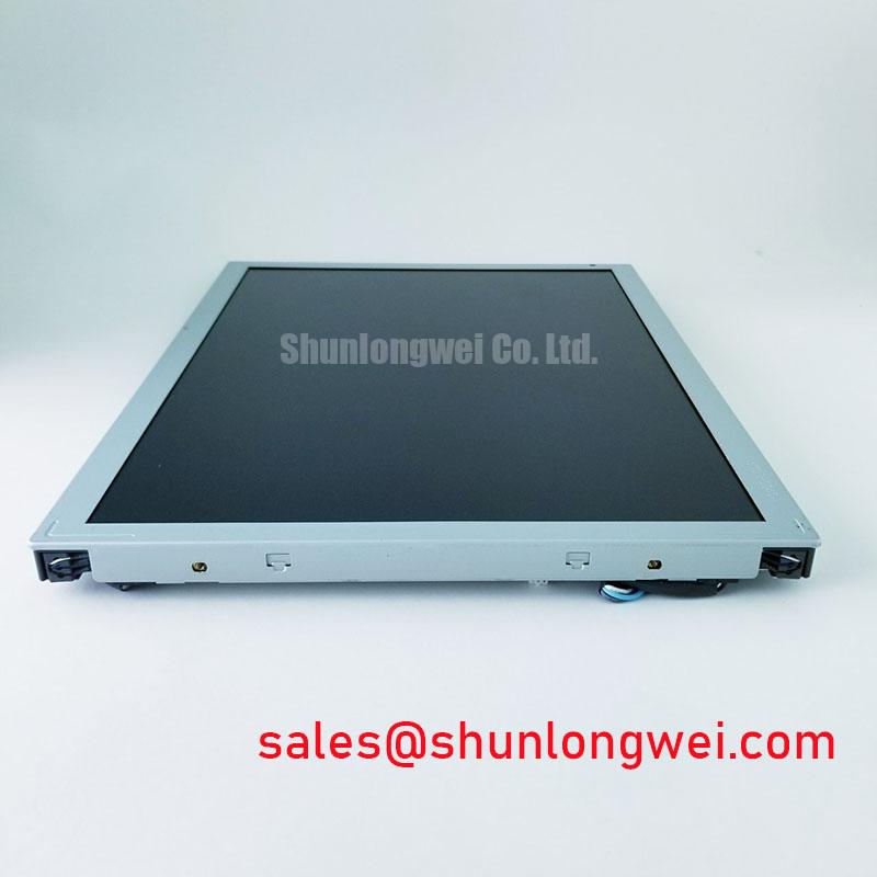
Begin the bench inspection by confirming the nameplate identity, checking the glass and bezel for visible damage, and comparing the installed connector arrangement with the replacement documentation before applying power. The LC150X01-A3K2 is an LG Display TFT-LCD Display Module classified for industrial LCD and HMI applications. The available factory information identifies the manufacturer, product category, display-module construction, and official specification status, but it does not provide verified electrical ratings, optical values, dimensions, pin assignments, or backlight data. The system integrator should verify those items against the original panel documentation before installation.
| Model | LC150X01-A3K2 |
| Manufacturer | LG Display |
| Product category | Industrial Grade LCD/HMI Panel |
| Construction | TFT-LCD Display Module |
| Specification status | Limited factory specification information available |
| Potential equipment evaluation | High-Voltage Substation Protection and SCADA Dispatch Console |
During service evaluation, place the panel on a clean, electrically safe work surface and inspect the glass edge, bezel interface, flexible connections, and visible driver-bond regions without applying point pressure. A three-stage primary-color bench test using red, green, and blue screens can help reveal intermittent lines, localized color loss, or nonuniform regions. The test should be performed with a known-good signal source and with the display observed at more than one brightness level.
A 45-degree flashlight inspection is useful when the powered display shows a suspected dark area. Reflected light can help distinguish an optical or illumination issue from a line defect associated with the glass-side driver connection. This observation is not a component-level failure verdict. Engineers should compare the affected area with a uniform test image, inspect the signal path, and repeat the test after the panel has reached a stable operating condition.
Available factory information for this model does not confirm a contrast ratio, anti-glare coating specification, or a validated sunlight performance value. Direct sunlight testing should therefore be treated as a system-level Design Consideration. Verify readability using the actual enclosure window, ambient illumination, viewing angle, and display settings. The industrial display technology background can be reviewed through The Ultimate Guide to Industrial TFT LCD Technology.
Field Alert: Disconnect power before removing or inserting the display cable, and do not twist the glass while aligning the module with the chassis.
Thermal Expansion Clearance Sizing across Heavy Industrial Metal Enclosure Cutouts
Before fitting the LC150X01-A3K2 into a metal control-panel opening, compare the original bezel envelope, active display area, connector clearance, mounting-hole pattern, and cable exit direction with the replacement assembly. The supplied factory data does not include verified mechanical dimensions, so the original panel drawing or a measured sample should control the cutout review. The opening must support the bezel without transferring enclosure distortion into the glass.
Cross-pattern fastening is a useful Design Consideration for distributing mechanical load. If the original equipment documentation specifies M3 fasteners, a general starting reference of 0.35 to 0.45 N·m may be evaluated only when it matches the chassis hardware, washer arrangement, thread condition, and panel manufacturer guidance. This is not an LC150X01-A3K2 factory specification. Final tightening should be validated by checking bezel seating, image uniformity, and mechanical stress after thermal cycling.
Interface compatibility requires more than connector appearance. Confirm whether the host uses LVDS or another display interface, then verify the lane arrangement, pixel-clock behavior, data mapping, signal polarity, connector keying, and power-sequencing requirements from the original panel documentation. JEIDA and VESA data-format alignment should be checked at the transmitter and receiver. If the replacement image has incorrect colors, unstable synchronization, or intermittent data, use an oscilloscope and a known-good signal path rather than assigning a single cause without measurement.
Backlight Luminance Control and Reliability Verification
The available specification context does not confirm the LC150X01-A3K2 backlight technology, luminous output, PWM input, analog dimming range, L70/B50 value, or permitted operating-temperature window. The original display manual must therefore determine the backlight driver type and control method. Do not connect a generic constant-current source or assume a familiar dimming interface solely from the module model.
For a SCADA dispatch console or substation protection terminal, evaluate luminance at the actual front-window position and under the enclosure’s thermal conditions. A Design Consideration is to provide an even mechanical support path around the display perimeter while avoiding pressure on the optical stack or glass. Heat-spreader rails may be considered only after thermal mapping identifies a local hot spot and the proposed structure has been checked for clearance, grounding, and mechanical stress.
Cold-environment testing should include image transitions, grayscale patterns, alarm text, and startup behavior at the intended system temperature. Liquid-crystal response can change with temperature, while heater-strip control can introduce local gradients or electrical noise. Engineers should record the panel temperature, supply behavior, backlight command, and image response together. Any L70 or B50 service-life claim must come from the applicable LG Display documentation or an identified test source; no field-life figure is established here.
Radiated Emissions Evaluation and Display Cable Grounding
Installing this display near high-voltage switching equipment requires system-level electromagnetic compatibility evaluation. The LC150X01-A3K2 itself should not be represented as independently compliant with CISPR Class A or Class B equipment limits. The complete console, including its power supply, controller, cable routing, enclosure, and grounding method, must be tested in its final configuration.
Begin by routing the display cable away from high-current switching loops and variable-frequency motor-drive wiring where the enclosure permits. Verify shield termination at the connector and chassis interfaces according to the host equipment design. A 360-degree shield connection may be considered when it is mechanically compatible and does not create an unintended current path. Common-mode ferrite components are also system-level options that require impedance, temperature, and signal-integrity evaluation.
Pixel jitter, horizontal noise bands, or unstable text should be investigated by comparing the display supply, frame timing, differential waveform, cable shield condition, and chassis potential. PWM frequency and duty-cycle linearity must be taken from the confirmed backlight documentation. If those values are unavailable, the integrator should not assume a 200 Hz to 1 kHz control range. Verify flicker, acoustic behavior, camera interaction, and luminance linearity on the assembled console.
💡 Pro Tip: Keep the differential display pair routing symmetrical and review clock and data timing at the receiver during temperature and noise testing rather than relying only on a continuity check.