

Content last revised on September 10, 2026
Logic Power and Liquid Crystal Bias Power Up Sequence Coordination
| Model | LM64183P |
|---|---|
| Manufacturer | Sharp |
| Product Category | Industrial Grade LCD/HMI Panel |
| Display Technology | FSTN / STN Monochrome Passive Matrix LCD Panel |
| Specification Status | Official Factory Spec Verified |
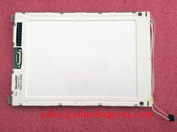
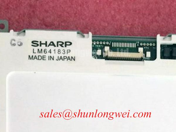
Probe the panel supply rails and controller timing signals at the display connector while observing the original equipment power up cycle, paying close attention to the order in which logic power, display bias, and image data become active. The Sharp LM64183P is an FSTN / STN monochrome passive matrix LCD panel, so stable bias conditions and disciplined controller timing are central to readable contrast and clean character rendering.
On legacy industrial HMI boards, a blank panel, unstable contrast, persistent background shading, or intermittent image appearance can originate in the display power sequence rather than in the LCD glass itself. Confirm that the host board enables its logic supply before it drives display control activity and that the liquid crystal bias network follows the timing expected by the original display controller. The system integrator should verify the required supply voltage from the original panel documentation.
Where the controller path provides frame, line, and dot clock signals, inspect their continuity and waveform stability at the connector rather than relying only on readings at the processor output. A damaged flex cable, contaminated connector contact, cracked solder joint, or loosened locking mechanism can allow a timing signal to reach the panel inconsistently. This may present as missing sections of text, unstable rows, flickering regions, or an image that changes when the cabinet door is moved.
Design Consideration: passive matrix panels depend on coordinated row and column drive timing to prevent an unwanted DC component from remaining across the liquid crystal material. During repair work, preserve the original control board architecture wherever possible and compare the timing path against a known functional channel when one is available. Avoid attaching or removing the display connector while the equipment is energized because residual bias conditions can complicate fault isolation.
Cold cabinet starts deserve extra attention. At lower temperatures, liquid crystal response can slow and apparent contrast may take longer to settle after power is restored. This behavior should be distinguished from an electrical fault by observing whether the image becomes stable as the equipment reaches its normal enclosure temperature. Repeated power cycling during this observation can obscure the result, particularly when the host controller retains display state or starts its bias network gradually.
When vibration is present, inspect the flexible circuit route for sharp bends, compression against enclosure edges, or strain transferred from a hinged front bezel. The cable should sit naturally when the panel is mounted, with no forced twist at the connector. Mechanical movement in the signal path can produce symptoms that resemble a controller failure, yet the source may be a connector latch that is no longer holding the flex circuit evenly.
Cleaning Zebra Rubber Strips and PCB Gold Contact Pads with Anhydrous Isopropyl Alcohol
Remove power, release the front bezel carefully, and inspect the zebra connector seating line for displaced elastomer, dust tracks, corrosion residue, or uneven compression before cleaning the contact surfaces. In monochrome passive matrix assemblies, missing lines or intermittent character areas can be associated with a poor pressure interface between the LCD contact edge, conductive elastomer, and the host PCB pads.
Use anhydrous isopropyl alcohol on a lint free applicator to clean accessible PCB gold contact pads without flooding nearby components. Follow the display assembly or equipment manufacturer’s guidance before applying solvent to the LCD contact region. Allow the cleaned surfaces to dry fully, then position the zebra strip straight and evenly across its complete contact length. The aim is to restore a clean electrical interface without stretching, cutting, or contaminating the elastomeric connector.
Reassemble the bezel so that clamping pressure is distributed across the display perimeter rather than concentrated at a single corner. Uneven frame loading can affect the optical appearance of an FSTN / STN panel, including local shading or visible nonuniformity. It can also shift a zebra connector enough to create intermittent rows or columns after vibration, thermal cycling, or repeated operator interaction with the front enclosure.
⚠️ Maintenance Note: Inspect the display gasket, bezel seating surfaces, and cabinet airflow path during scheduled maintenance because trapped dust and uneven compression can affect both connector reliability and visible panel uniformity.
Do not scrape contact pads with abrasive tools or use aggressive cleaning chemicals. A contact surface may look clean while still being mechanically damaged or insufficiently supported by the bezel. After reassembly, test the screen with its normal operating page set, including dense text fields, fixed symbols, and changing values. A basic startup screen alone may not exercise every row and column path.
Contrast problems should be assessed separately from missing line faults. A panel with complete characters but weak or washed out viewing performance may point toward the host bias circuit, temperature compensation path, or optical aging. A panel with sharply defined missing regions may instead warrant closer examination of connector alignment, board pad condition, flex continuity, and mechanical clamping. These checks prevent a single visual symptom from being assigned to one assumed cause.
For field maintenance teams evaluating a same class display during an equipment repair, LQ10D321 can be reviewed as a separate compatibility candidate. Mechanical fit, optical requirements, controller interface, power arrangement, mounting geometry, and host firmware behavior must all be verified at system level before any substitution decision is made.
Polarizer Aging, UV Exposure, and Contrast Preservation
Inspect the front viewing surface under normal ambient light for discoloration, haze, edge lifting, bubbles, or changes in contrast that remain visible after the display has reached a stable operating temperature. The LM64183P uses monochrome FSTN / STN passive matrix technology, and the visible optical stack should be evaluated as part of the assembly rather than treating every faded image as an electrical drive failure.
Long term exposure to strong ambient light, ultraviolet energy, heat, humidity, cleaning agents, and airborne contaminants can alter the appearance of a legacy display window or polarizing surface. Engineers should document whether the issue is limited to the display area, appears across the entire viewing window, changes with angle, or is accompanied by physical deformation. This establishes whether the problem is likely related to the front optical path, enclosure contamination, display drive condition, or a combination of factors.
A navigation or monitoring terminal installed near windows, exterior access points, or high illumination areas may require careful enclosure inspection as part of a display service event. This is a compatibility evaluation example rather than a declared application rating for the panel. The surrounding equipment designer remains responsible for sealing, sunlight exposure control, thermal management, salt contamination protection, and operational verification.
At low temperatures, slower liquid crystal response can make pages appear to update gradually or temporarily show less distinct contrast. Allowing the equipment to stabilize at its intended operating condition helps distinguish temperature related response changes from permanent optical degradation. If image quality varies strongly with temperature, inspect the host temperature sensing and bias compensation circuitry where applicable, using the original equipment documentation as the authority for expected behavior.
Static display pages deserve practical attention during preventive maintenance. Operators often leave alarms, setpoint pages, status maps, or fixed navigation layouts visible for extended periods. Rotate test pages during service to observe whether all characters, graphics, and background regions respond consistently. Any retained image appearance should be recorded with the panel temperature, screen content, viewing angle, and power state so that later checks can be compared objectively.
Mechanical sealing also affects optical reliability. A compressed or degraded front gasket can permit dust or moisture to reach the panel cavity, while excessive bezel force can introduce local stress patterns that look like contrast defects. Tighten the enclosure according to the equipment manufacturer’s mechanical procedure and verify that the display sits flat without twist. Do not infer a panel mounting torque where the original assembly specification does not provide one.
For broader background on display technologies, selection factors, and service misconceptions, consult The Ultimate Guide to Industrial TFT LCD Technology. Its general engineering context can help teams separate interface, optical, enclosure, and environmental questions during a controlled display evaluation.
Backlight Ballast and Tube Current Verification in Legacy Display Assemblies
Inspect the original equipment schematic and physical panel assembly to establish whether the complete display system includes a separate illumination subsystem before testing any high voltage ballast circuit. The official verified information for LM64183P identifies the panel as an FSTN / STN monochrome passive matrix LCD panel; the system integrator should verify the required illumination arrangement from the original panel documentation and host equipment design.
Where a legacy terminal uses a separate lamp, inverter, or ballast assembly, isolate the diagnosis between the LCD image path and the illumination path. A screen can contain valid image data while remaining difficult to see because the external lighting system is inactive. Conversely, a lit viewing area with no stable characters requires examination of display bias, controller timing, connector integrity, and panel contact pressure.
High voltage lighting assemblies require disciplined safety practice. Disconnect the equipment from its energy source, allow stored energy to discharge according to the host equipment service procedure, and use appropriately rated instruments when a powered measurement is necessary. Do not handle lamp wiring, ballast outputs, or associated connectors as low voltage logic connections. Their operating behavior, insulation spacing, and measurement method are determined by the original system design.
Inspect capacitor condition, connector retention, insulation wear, cable routing, and signs of heat exposure around any external ballast assembly. These observations can reveal a service issue, but they do not establish a single cause without circuit measurement. Compare the supply input, enable behavior, output stability, and load connection against a known functional system when possible. Changes in brightness can also result from enclosure contamination, aging optical films, power supply behavior, or the host controller’s illumination control signal.
After display service, confirm that the bezel does not pinch the flex circuit or press unevenly against the LCD edges. A repair that restores illumination but introduces connector stress can create later row, column, or contrast faults. Close the enclosure in stages, observing the display after each fastening point is secured, and check that the screen remains stable when the cabinet experiences normal handling vibration.
For marine radar and navigation bridge console maintenance evaluations, engineers should treat the Sharp LM64183P as a display assembly requiring full interface, mechanical, optical, and enclosure compatibility checks. Salt exposure, moisture ingress, vibration, lighting conditions, and power quality are system conditions that must be assessed at the equipment level rather than assigned as intrinsic performance claims for the LCD panel.