

Content last revised on September 22, 2026
Eye Diagram Voltage Margin and Differential Noise Floor Verification in High Vibration Bays
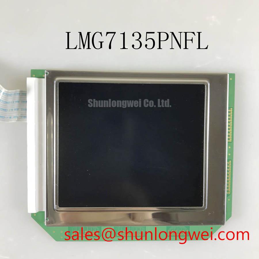
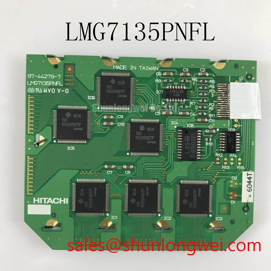
Begin incoming inspection with the panel unpowered: compare the label and connector position with the original unit, inspect the TFT glass and bezel for visible damage, and confirm the replacement identity as LMG7135PNL before connecting any cable. This product is identified as a KOE / Hitachi Industrial Grade LCD/HMI Panel with a TFT LCD Display Module enclosure format. The supplied product record does not include a complete set of factory specifications.
Because the supplied product record does not provide a confirmed resolution, active area, supply voltage, interface pinout, backlight type, touch function, luminance value, or operating temperature range, those details should be checked against the original panel documentation before installation. The system integrator should verify the required supply voltage from the original panel documentation rather than assume compatibility from the model number alone.
| Model | LMG7135PNL |
| Manufacturer | KOE / Hitachi |
| Product category | Industrial Grade LCD/HMI Panel |
| Construction format | TFT LCD Display Module |
| Specification status | Complete factory parameter record not supplied |
| Primary evaluation point | Panel identity, mechanical fit, interface compatibility, and optical condition |
For a repair bench evaluation, first isolate the display from the machine harness and examine the cable route, connector seating, shield termination, and chassis bonding arrangement. A display that operates correctly on a short bench cable can behave differently beside variable frequency motor drives, servo amplifiers, contactors, or high current switching conductors. This does not establish a fault in the panel itself; it indicates that the complete signal path requires verification.
If the original assembly uses LVDS or another differential display interface, the integrator should confirm the exact signaling standard and pin assignment from the source panel documentation. Do not assume that a visually similar connector has the same pin order. Check the known good signal path with an oscilloscope suitable for differential measurements, observing eye opening, common mode behavior, edge distortion, and any timing disturbance that appears when nearby drives are enabled.
A 360-degree shield termination can be considered where the cable construction and equipment grounding design support it. This is a Design Consideration, not an official specification of the LMG7135PNL. Ferrite components may also be evaluated as part of the finished cable assembly when conducted or radiated interference is present, but their impedance profile, placement, and effect on the signal waveform must be established by system testing. Adding suppression without checking the differential waveform can reduce noise in one operating condition while affecting signal quality in another.
Horizontal noise bands, unstable pixels, or intermittent image updates should be investigated across the entire chain. Record the display behavior with the machine idle, with the motor drive enabled, during acceleration, and during regenerative operation. Inspect the cable clamp points and connector latch after vibration testing. Signal integrity, grounding, power quality, and mechanical connector retention can produce overlapping symptoms, so the panel should not be assigned a single cause without comparative measurements.
For cold equipment bays, designers should verify the panel’s documented temperature limits and the controller’s startup sequence. Liquid crystal response can change at low temperature, while the host timing source and cable characteristics can also shift with the environment. Heater control, if present in the equipment, should be validated against the original system documentation. No heater rating or low temperature operating limit is assigned here because it is not included in the supplied factory parameter record.
Suppressing Localized Thermal Gradients to Protect Optical Uniformity
Inspect the entire active image with a uniform white field, a dark field, and several intermediate gray fields. This incoming QA check helps separate a panel defect from reflections, cable problems, image source artifacts, or enclosure pressure. Look for fixed bright points, dark points, line defects, uneven illumination, edge shading, and color variation that remains in the same physical location when the input image changes.
Thermal management should be treated as a system integration issue. A metal rail, bracket, or nearby power device can create a local temperature gradient if it contacts the bezel or restricts airflow around one edge. The appropriate mechanical solution depends on the chassis, mounting surfaces, heat sources, and approved panel drawings. Do not infer the material, optical stack, light guide construction, or LED lifetime rating of the LMG7135PNL without a manufacturer document confirming it.
For installations near high intensity lighting or observation windows, the optical surface should be checked for reflections and readability under the actual enclosure lighting. Anti glare or anti reflection treatment must be confirmed from the original panel specification rather than assumed. If a cover lens, protective window, or touchscreen is added, evaluate its reflection, haze, transmission, cleaning compatibility, and pressure on the display assembly as part of the complete HMI design.
The supplied product data does not confirm a resistive or capacitive touch layer. If the replacement is being considered for a touch enabled medical or industrial console, the system integrator should verify whether the original assembly uses a separate touch sensor, an integrated touch panel, or no touch function. Glove operation and wet finger response are properties of the complete touch system, controller, cover lens, and firmware, not conclusions that can be made from the LMG7135PNL model identifier alone.
Clock jitter, data hold timing, and transmitter compatibility should be checked at the interface actually used by the host controller. When the system uses TTL or LVDS, confirm the electrical requirements from the original documentation and compare the replacement signal response with a known good panel. A timing problem may appear as flicker, unstable transitions, or missing image content, but those symptoms can also result from incorrect power sequencing or connector contact resistance.
Wide Temperature Operational Margin and Sub Zero Liquid Crystal Response
Do not label this panel as suitable for a specific temperature range unless that range is confirmed by the applicable factory document. For an industrial replacement evaluation, place temperature qualification around the actual equipment envelope and monitor startup, image stability, luminance consistency, pixel response, and connector behavior at each condition. The result should be recorded as system test data rather than presented as an LMG7135PNL factory rating.
At reduced temperature, liquid crystal movement can become slower and gray to gray transitions may appear extended. This is a general display technology consideration. It does not prove that the LMG7135PNL has a particular response time or low temperature limit. Engineers should compare moving test patterns with static patterns and inspect whether the observed behavior clears as the panel reaches its normal operating condition.
At elevated temperature, assess localized heating around the backlight driver, controller board, enclosure wall, and any nearby power components. The display assembly should not be pressed against a warm surface unless the mechanical and thermal drawings permit that arrangement. If the equipment uses a constant current backlight driver, verify its output requirements, startup behavior, dimming method, and protection functions against the panel documentation.
Backlight service life must not be estimated from a generic LED lifetime statement. The supplied record does not provide an L70, B50, MTBF, brightness maintenance curve, or backlight operating limit for this model. Where service planning is important, request the applicable factory data and test the complete display assembly under the intended drive current, ambient condition, duty cycle, and enclosure airflow.
For a surgical navigation display or ultrasound diagnostic terminal, optical consistency should be judged with the equipment’s real image content as well as standard test fields. Confirm grayscale visibility, edge detail, color stability, and readability through any protective window. Medical equipment qualification, EMC compliance, and safety certification belong to the finished system and cannot be claimed for this display module alone.
💡 Bench Tip: Disconnect power before inserting or removing the display cable, use ESD protection, and confirm that the flexible cable is fully aligned before locking the connector.
Flush Mount Open Frame Bezel Integration and Perimeter Gasket Shock Isolation
Before cutting or modifying a chassis, compare the original panel’s outer envelope, visible area, connector clearance, mounting points, and cable bend path with the replacement documentation. The supplied record identifies the enclosure format as a TFT LCD Display Module but does not provide confirmed external dimensions or fastener details. These dimensions should therefore be measured from the original equipment or obtained from the applicable mechanical drawing.
A flush mount design should support the bezel without concentrating force on the active glass or display edge. A gasket can be evaluated as a mechanical isolation feature when it is compatible with the approved mounting geometry, but its compression, thickness, material, and environmental resistance must be selected by the system designer. Avoid using the bezel as a structural clamp unless the original design explicitly allows it.
Fastener torque is a system controlled installation value, not a confirmed LMG7135PNL factory parameter in the supplied information. If the chassis uses threaded fasteners, apply the equipment manufacturer’s documented torque and tighten progressively in a cross pattern where appropriate. After assembly, run a dark field and uniform field inspection to check for pressure related shading, edge nonuniformity, or changes that occur when the frame is tightened.
In high EMI factory environments, differential pair routing should preserve the interface arrangement specified by the original display documentation. Keep high speed display conductors separated from noisy power wiring where the machine layout permits, avoid unnecessary cable loops, and maintain connector strain relief. If the documentation specifies controlled impedance or skew requirements, validate the assembled cable and host board against those requirements rather than applying a generic value.
For a same size or same resolution comparison, the TX23D11VM2BAA can be reviewed as a separate product record. It should not be treated as a direct substitute until dimensions, interface, optical characteristics, mounting, and electrical requirements have been matched against the original panel.
Additional integration factors for industrial HMI assemblies, including grounding, enclosure sealing, vibration control, optical readability, and service access, are discussed in Industrial Display and HMI Solutions. For LMG7135PNL replacement work, the final acceptance decision should be based on documented interface compatibility and measured performance in the target equipment.