

Content last revised on October 15, 2026
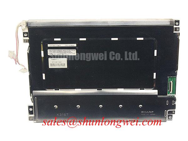
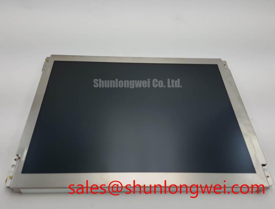
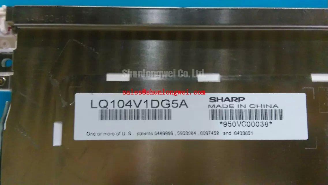
LQ104V1DG5A Sharp TFT LCD Active Matrix Color Display Module
During a CNC operator panel or robot teach pendant repair, first isolate the display supply and inspect the panel connector, cable seating, bezel pressure, and signal path before applying power. The LQ104V1DG5A is identified as a Sharp TFT LCD active matrix color display module. Electrical interface, timing, optical, and mechanical values must remain aligned with the original equipment documentation when assessing a replacement.
This module is evaluated by industrial maintenance teams when a control-panel display shows intermittent image loss, unstable brightness, horizontal noise, or mechanical incompatibility after service work. It may be considered for CNC operator panels, robot teach pendants, industrial HMI consoles, and monitoring assemblies, subject to confirmation of the host system’s connector, power, video protocol, backlight, and mounting geometry.
| Item | Product information | Integration relevance |
|---|---|---|
| Manufacturer | Sharp | Match the replacement against the equipment service record and original panel documentation |
| Part number | LQ104V1DG5A | Use the complete ordering code when checking physical and electrical compatibility |
| Product category | LCD display module | Verify suitability for the intended control-panel assembly |
| Construction classification | TFT-LCD Active Matrix Color Display Module | Check the host controller’s video architecture and panel timing requirements |
| Mechanical compatibility | Requires verification against the exact panel drawing | Confirm dimensions, connector position, interface, backlight, and mounting details before installation |
Eye-Diagram Voltage Margin and Differential Noise Floor Verification in High-Vibration Bays
Pixel jitter near variable-frequency motor drives should be investigated as a complete signal-integrity problem rather than assigned to the LCD panel alone. Begin at the display connector and trace the cable route toward the controller, looking for loose shield termination, poorly bonded chassis points, damaged foil, excessive bend stress, or routing that places the video cable alongside motor output conductors.
The LQ104V1DG5A is catalogued as an active matrix color display module, but the supplied product data does not establish whether the host connection uses LVDS, TTL, or another panel interface. The system integrator should therefore compare the original panel pinout, connector keying, pixel clock arrangement, data mapping, and power sequence before selecting a controller or cable assembly. A connector that fits mechanically can still be electrically incompatible.
For an LVDS-based host, evaluate the complete differential path with the original cable length, connector transition, shield termination, and receiver reference plane in place. Differential pairs should remain closely coupled and should avoid unnecessary stubs. Controlled impedance is a board and cable design requirement determined by the transmitter, receiver, dielectric structure, and interconnect geometry; it is not an independently confirmed specification of this display model. For a TTL implementation, review single-ended reference integrity, return-current continuity, edge rate, and clock-to-data timing at the panel connector.
Use a known-good signal path as the comparison reference when an oscilloscope or suitable differential probe is available. Observe the clock and data relationship at the receiving end rather than judging only the controller output. A visibly clean waveform at the source can become marginal after cable routing, shield discontinuity, connector oxidation, or chassis movement. Temperature changes and vibration can also alter contact pressure and cable position, so a static bench result should not be treated as a complete industrial qualification.
For equipment operating near high-frequency motor switching, a 360-degree cable shield termination can provide a low-impedance path for high-frequency shield currents, provided that the cabinet bonding strategy supports it. Ferrite suppression is a system-level design consideration rather than a confirmed accessory supplied with the Sharp module. Its selection should follow measured interference behavior, cable construction, common-mode current, and the required signal bandwidth.
When comparing the Sharp unit with the same-size-class LQ104V1LG81, engineers should compare the complete panel documentation rather than relying on diagonal size or connector appearance. Resolution, pin assignment, power requirements, backlight control, timing, and mounting features must all agree with the host equipment.
💡 Pro Tip: Keep differential pairs referenced to a continuous return path and review clock-to-data timing at the panel connector after the cable is installed in its final cabinet position.
Investigating Frame Lag and Image Smearing in Cold Storage and Outdoor Industrial Facilities
Sub-zero operation can make motion artifacts more noticeable because liquid-crystal response is temperature-dependent, while cable insulation, connector contact force, and enclosure materials also change with temperature. For the LQ104V1DG5A, temperature range, gray-to-gray response, contrast behavior, and optical compensation must be taken from the applicable Sharp documentation or the equipment’s approved panel record rather than inferred from the product category.
When a display appears to retain a previous image during cold startup, record the time from power application to stable image, the ambient temperature, the displayed pattern, and the controller’s frame activity. A slow visual transition may involve panel response, controller timing, backlight startup, or image-processing behavior. Testing should separate these variables by using static fields, moving patterns, and the original controller under the same operating conditions.
Outdoor and refrigerated installations also place stress on seals, cable exits, and front-surface interfaces. Inspect the perimeter for compression, contamination, or signs of moisture ingress after thermal cycling. Do not assume that an industrial-grade category alone confirms a specific ingress rating, outdoor optical treatment, heater provision, or condensation tolerance. Those characteristics belong to the complete assembly qualification.
Anti-glare and anti-reflection treatments can affect perceived sharpness, black level, and sunlight readability. The available product classification does not confirm a particular AG or AR surface treatment. If the panel is installed behind a protective window, assess the combined optical stack, including reflections from the window, bezel, air gap, and ambient light source. A high-brightness backlight cannot by itself correct excessive front-surface reflection.
Touch capability should also be treated as a host-system question. The product is identified here as an LCD module, but the supplied specification does not confirm a resistive or capacitive touch layer, glove operation, water rejection, or touch controller interface. For a replacement in a touch-operated pendant, verify the touch overlay, controller, bonding method, active area, and front-bezel clearance as separate compatibility items.
High-Voltage Striking Potential and Secondary Coil Insulation Testing
Backlight troubleshooting must begin by identifying the installed backlight architecture rather than assuming that every display module uses the same driver method. The supplied classification for the LQ104V1DG5A does not confirm CCFL ignition voltage, LED string voltage, PWM range, constant-current requirements, or a specific backlight connector pinout.
If the service assembly uses a high-voltage lamp inverter, insulation testing must follow the approved procedure for the specific circuit or component under test. Isolate components as that procedure requires, use equipment rated for the test, and follow the safety limits established by the responsible engineering organization. Audible buzzing may arise from an inverter, transformer, mounting resonance, or mechanical contact; it should be localized with the circuit energized only under controlled conditions.
If the system uses an LED backlight, inspect the driver’s current regulation, enable behavior, dimming waveform, connector polarity, and thermal path. A replacement display may require a different driver even when the mechanical opening appears identical. PWM dimming quality should be judged at the LED driver and at the visual output, checking for visible flicker, beat frequencies, and interaction with camera-based inspection systems.
Brightness half-life and service life depend on specified test conditions and cannot be assigned to this part without an applicable source. Evaluate the backlight under the actual current, ambient temperature, enclosure condition, duty cycle, and brightness setting used by the equipment. The technical background in The Ultimate Guide to Industrial TFT LCD Technology can support broader TFT-LCD selection work, while the exact backlight arrangement still requires product-specific documentation.
For an existing cabinet, trace the complete chain from power entry to backlight driver and then to the panel. Check whether the controller expects a separate enable signal, analog brightness input, or digital dimming command. Do not connect an assumed LED driver to a panel with an unverified backlight topology. A visually similar replacement can fail immediately if the driver architecture, polarity, or startup sequence differs.
The related NL6448BC26-27D may be reviewed as a separate display solution when engineers are comparing panel and backlight arrangements. It should be treated as a distinct product evaluation, not as an automatic electrical substitute for the Sharp unit.
Sharp’s display resources, including the Sharp Devices Europe portal and the Sharp Display Solutions official portal, provide reference points for display-system assessment. Confirm the correct document set for the exact part number and revision before approving a backlight or inverter change.
Chassis Fastener Loading and Optical Mura Defects
Dark corners, bright patches, and uneven fields after installation should first be correlated with bezel contact, frame flatness, gasket compression, and screw loading. The supplied product data identifies a TFT-LCD module but does not provide the chassis drawing, fastener torque specification, active-area dimensions, bezel envelope, or approved mounting tolerance for this part.
Install the display against a flat, clean support surface and confirm that the opening does not contact the active area or edge seal. Fasteners should draw the frame evenly rather than force a warped chassis into position. A cross-pattern tightening sequence is a general mechanical design consideration for distributing load, not a Sharp factory installation specification for this model.
Optical mura can become more visible when a frame presses locally against the panel, when a gasket is uneven, or when the enclosure twists during door closure. Compare a uniform gray field before and after each mechanical change. If the artifact moves with bezel pressure, investigate the enclosure geometry and support points before replacing electronic components.
Use the original mounting hardware only after checking thread engagement, washer condition, spacer height, and frame clearance. A fastener that bottoms out can register tightening torque without securely clamping the frame and may damage the mounting point. The permitted torque must come from the panel drawing or equipment assembly specification; it should not be inferred from thread size alone.
For CNC panels and robot teach pendants, review the complete front assembly: protective window, gasket, touch overlay, bezel, display frame, and cable bend radius. These parts can alter both optical uniformity and connector stress. Designers should verify the final assembly through powered inspection, mechanical cycling, and temperature exposure appropriate to the equipment duty.
Before releasing a replacement, record the panel identification, connector orientation, controller settings, backlight behavior, mounting stack, and image test result. This creates a practical service baseline for future maintenance without treating unverified interface or lifetime values as fixed characteristics of the module.