

Content last revised on November 3, 2026
Sharp LQ104V1DG71 Display Identification and Initial Checks
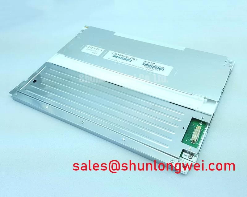
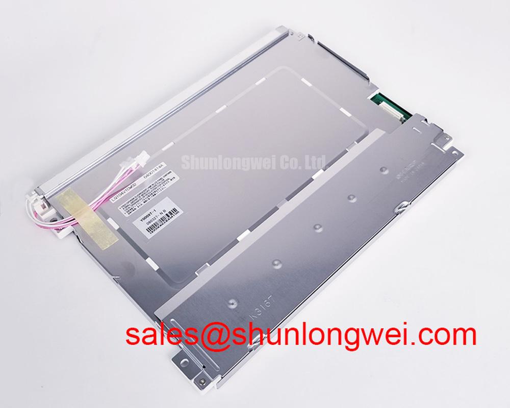
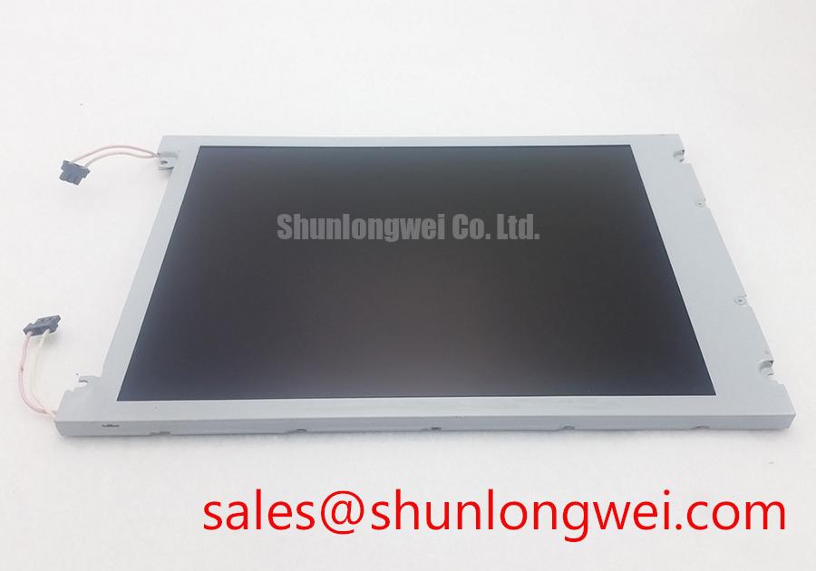
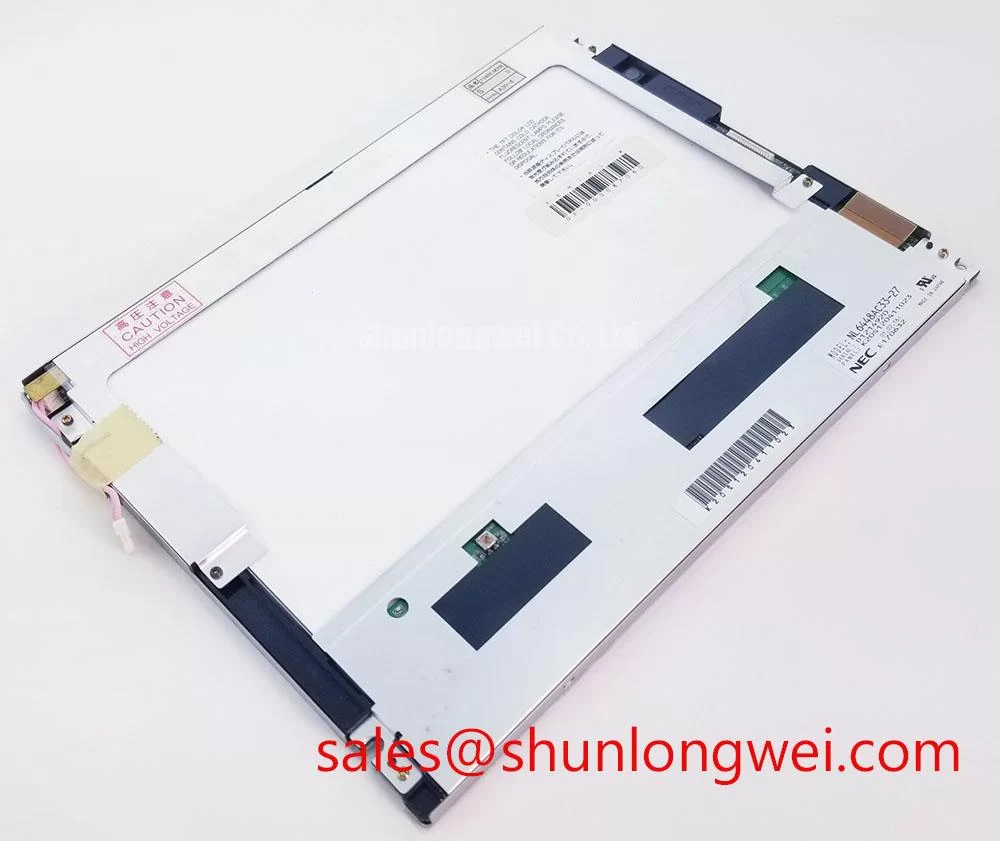
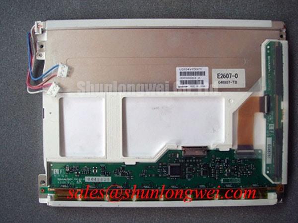
With the machine powered down, inspect the panel connector and cable seating before disturbing the display assembly; then compare the panel label and host wiring against the equipment’s service documentation. The Sharp LQ104V1DG71 is a 10.4-inch LCD with 640 × 480 VGA resolution, a 31-pin parallel RGB, 1-channel, 6-bit interface, and dual separable CCFL lamp assemblies. These specifications define the panel’s documented interface and format, not the complete electrical requirements of the host display system.
A black screen, a dim image, or missing color can involve different parts of the display chain. Check the host’s video output and panel supply separately from the CCFL inverter and lamp connections. A lit backlight without a visible image directs attention toward video signaling, cable seating, and host timing; an image that is difficult to see under normal lighting makes the backlight path worth checking. Treat these observations as diagnostic branches, not one-to-one fault codes.
The panel’s specified supply is 3.3 V / 5.0 V typical. Confirm which supply setting the original system uses before connecting a replacement panel. Do not infer connector pin assignments or backlight drive requirements from the connector’s pin count alone.
Viewing Direction, Grayscale Appearance, and RGB Image Checks
For image complaints, first distinguish a viewing-angle or grayscale appearance change from a loss of video data. The LQ104V1DG71 is specified as normally white and transmissive, with 262K colors at 6 bits per color and an optimum viewing direction at 6 o’clock. Those are documented optical characteristics. A dynamic contrast ratio, TN mode, IPS or MVA construction, symmetric viewing cone, anti-glare treatment, and temperature-dependent contrast curve are not specified here, so they should not be used as assumptions when assessing this part.
Compare the image with the operator viewing the display from its intended direction and under consistent ambient lighting. If grayscale steps appear uneven or colors are missing, inspect the parallel RGB data path and host configuration. The panel uses a 1-channel, 6-bit parallel RGB interface; it is not identified as an LVDS panel. LVDS impedance, JEIDA/VESA mapping, and LVDS clock-jitter limits therefore cannot be applied as panel specifications. For general context on the VGA form factor, see Display Aspect Ratio and Standard Screen Form Factors.
When evaluating this display for an AGV or forklift telematics console, designers should check viewing position, enclosure window, ambient light, and the host’s RGB timing together. A panel’s resolution and color depth alone do not establish readability or suitability for a particular vehicle installation.
Mechanical Fit and Clearance in Heavy Industrial Metal Enclosures
Use the specified outline and active-area dimensions when checking a replacement against the existing bezel and chassis opening. The LQ104V1DG71 measures 246.5 mm wide × 179.4 mm high × 14.2 mm deep, with an active area of 211.2 mm × 158.4 mm. Its diagonal is 10.4 inches (26 cm). Verify the available opening, retaining features, cable bend clearance, and depth envelope against the actual assembly drawing; these panel dimensions do not define chassis tolerances or mounting-hole locations.
Do not transfer a generic fastener torque or cutout tolerance to this panel as though it were a manufacturer specification. As a Design Consideration, seat the assembly evenly and avoid forcing the bezel or chassis against the display. If a comparison candidate is being considered, LQ104S1LG61 is a related model to evaluate, not a confirmed drop-in replacement on the basis of the information presented here. Check its mechanical drawing, interface, supply, optical characteristics, and backlight arrangement against the equipment documentation before substitution.
Cold or hot operating conditions can affect the behavior of an LCD system, but no operating-temperature range or gray-to-gray response specification is included in the parameters above. For vehicle installations, validate the complete assembly in its intended enclosure and operating environment. The product-level dimensions do not establish thermal expansion allowances for a metal cutout.
Logic Supply Voltage (3.3 V / 5.0 V) and Connection Checks
Before powering the panel, confirm the host’s selected logic supply and connector pinout against the original panel documentation. The documented supply is 3.3 V / 5.0 V typical; this does not establish that either setting is interchangeable in every host design. The system integrator should verify the required supply voltage from the original panel documentation.
Trace the video path from the host output through any adapter or cable to the panel connector. This model is specified for parallel RGB, 1-channel, 6-bit signaling. Do not troubleshoot it as though the panel interface were LVDS, or apply LVDS differential-pair impedance and JEIDA/VESA mapping assumptions without evidence that the host contains a separate conversion stage. Check the host timing configuration and signal integrity using the equipment’s known-good design data.
Field Alert: Disconnect system power before inserting or removing the panel cable to reduce the risk of electrical disturbance at the connector.
For a replacement assessment, compare the full signal and mechanical requirements rather than matching diagonal size alone. The linked LQ104V1DG5B page can serve as a reference for a related display evaluation, but its presence does not establish compatibility with the LQ104V1DG71 or with a particular CCFL inverter. Check lamp connections and inverter requirements from the system documentation.
Assessing Image Response and Backlight Behavior during Cold Start
At cold start, assess whether the reported issue is slow image transition, a generally dim display, or loss of the image itself. These symptoms point to different checks: observe motion and grayscale transitions for response behavior, verify the CCFL assemblies and inverter path for illumination, and inspect the RGB path if the backlight is present but image data is absent. The LQ104V1DG71 is specified with dual separable CCFL lamp assemblies; LED-backlight assumptions do not apply to this stated configuration.
Response time, operating-temperature limits, thermal-cycle limits, sealant characteristics, and any permitted heater control profile are not part of the supplied product parameters. Avoid assigning a numeric cold-start threshold to the panel without its applicable manufacturer data. When integrating the display in mobile equipment, designers should validate the complete host and enclosure across the actual operating conditions, including cable behavior and backlight operation.
If the display is being replaced during a field repair, record the panel label, connector orientation, host supply setting, and lamp configuration before removal. For broader integration context covering industrial display and HMI checks, consult Industrial Display & HMI Solutions.