


Content last revised on September 10, 2026
Logic Supply Voltage Sequencing and Interface Verification
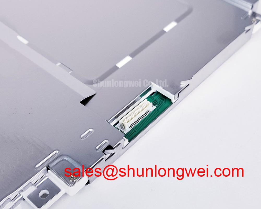
Begin interface work by identifying the original controller board and its panel cable without assuming a particular logic voltage, signaling method, or data mapping. The system integrator should verify the required supply voltage, logic sequencing, and display interface from the original LQ104V1DW02 panel documentation and the host equipment schematic. This step is particularly important when a panel powers without forming a stable image, because an apparently active display can still be receiving an incompatible signal format or incorrect timing relationship.
Design Consideration: display logic circuits can be sensitive to the order in which power, enable, and data signals become valid. During bench diagnosis, technicians should observe the controller output and panel supply behavior with appropriate instruments while following the equipment manufacturer’s isolation procedure. Check whether the panel cable is fully seated, whether its locking feature is engaged, and whether the cable has been creased sharply near the connector. Repeated flexing at a cable exit point can create intermittent faults that resemble controller instability.
Where the host uses differential display signaling, verify that the cable assembly, transmitter configuration, and receiving panel documentation agree on the required channel arrangement and mapping convention. Split images, repeated vertical sections, incorrect colors, flicker, or an image that is present but misaligned may indicate a mapping, timing, cable, or grounding issue. They should not be assigned to one cause without measurement. Compare the waveform path and signal integrity with the known working equipment configuration before replacing associated electronics.
Cold equipment start conditions require particular care. In a low temperature cabinet, condensation, cable stiffness, connector contact condition, and the response of the host display controller can all affect startup behavior. Allow the assembly to stabilize within the equipment’s specified environmental procedure before deciding that a display module has failed. If moisture is suspected, inspect enclosure seals, cable entry points, and the rear surface of the module for environmental exposure rather than applying power repeatedly.
For an existing HMI repair, a panel such as LMS700KF01-001 can be reviewed as a separate service item only after its exact interface, mechanical, optical, and electrical requirements have been checked against the original system documentation. It should not be assumed to be interchangeable with the LQ104V1DW02 solely because it appears relevant to an industrial display repair.
Backlight Power Path Inspection and Ignition Fault Isolation
The LQ104V1DW02 product identification confirms a TFT LCD Display Module, but the provided factory specification context does not establish a backlight technology, lamp count, inverter arrangement, dimming method, brightness rating, contrast ratio, surface treatment, or service life value. The system integrator should verify those details from the original panel documentation before selecting a test source, ordering a related power assembly, or changing the host backlight control circuit.
In field repair, separate the image formation path from the illumination path. A panel may show a faint image under controlled inspection while its backlight power chain is unavailable, or it may be illuminated while receiving no usable display data. Inspect the host power board, harness condition, backlight enable path, and control signal behavior in accordance with the equipment schematic. If the original application uses a high-voltage backlight circuit, only personnel qualified for that equipment should conduct measurements or disconnection work.
⚠️ Maintenance Note: De-energize the equipment and allow stored energy in the display power section to discharge according to the host service procedure before handling panel cables or backlight connections.
Acoustic noise, brightness cycling, delayed illumination, or periodic image dimming should be treated as observed symptoms rather than proof of a single defective part. Loose cable shielding, power converter behavior, aging of external support circuitry, thermal stress in the cabinet, or a command signal issue may contribute. Record whether the symptom changes with cabinet temperature, vibration, display brightness command, or cable movement. That record gives the repair team a more useful basis for deciding whether the panel itself, the controller, or the power subsystem requires further investigation.
For outdoor machinery display positions, direct ambient light and enclosure heat can reduce perceived readability even when the electronic display path remains functional. Designers should evaluate the installed viewing angle, glazing condition, enclosure ventilation, and the original optical specification. Do not infer sunlight performance, anti-glare treatment, or contrast performance for the LQ104V1DW02 without the applicable Sharp documentation.
Static HMI pages also deserve operational attention. Operators often leave status screens, alarm layouts, and machine diagrams unchanged for extended periods. Design Consideration: the equipment owner should use the display controller features available in the original system, such as approved screen management or standby behavior, where supported, and should assess any persistent image retention through normal service inspection rather than assuming it is permanent panel damage.
Industrial Bezel Fit, Seal Compression, and Mounting Stress Control
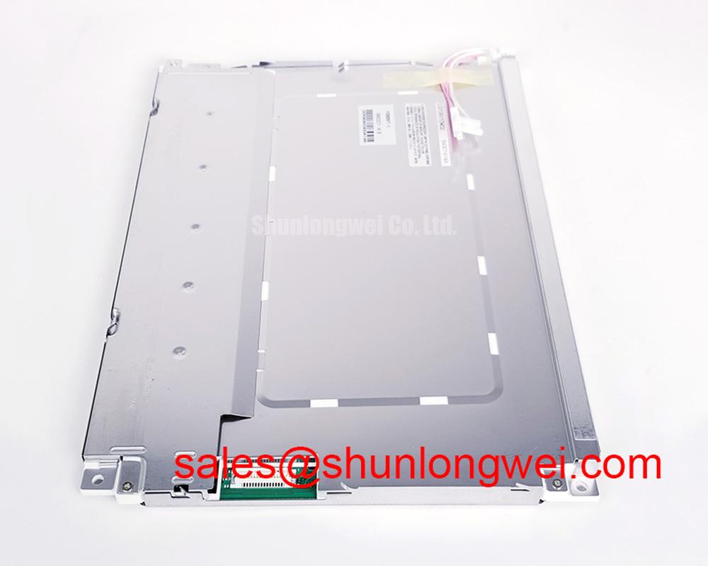
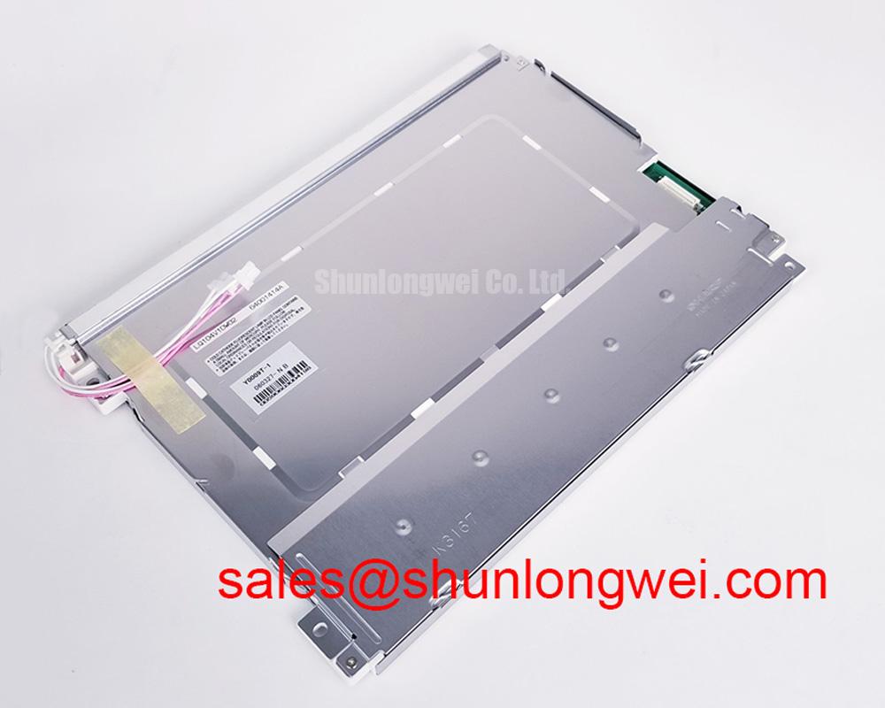
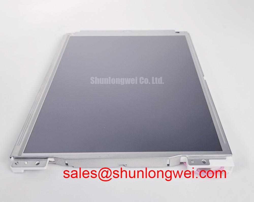
Mechanical inspection starts at the front bezel and proceeds to the rear support structure. Confirm that the LQ104V1DW02 sits squarely in its intended opening, with no foreign material trapped between the panel, bezel, gasket, and support frame. A display can be electrically correct while presenting localized light or shade variations if the enclosure applies uneven pressure around the viewing area. This type of optical nonuniformity is often more visible on dark or uniform test screens.
Design Consideration: mounting fasteners should be tightened in a balanced cross pattern using the torque requirement specified by the equipment manufacturer or the original panel assembly documentation. Avoid using a generalized torque value as a substitute for the approved mechanical requirement, because screw size, frame material, thread engagement, gasket design, and bracket geometry determine the acceptable load. If a panel is removed, inspect whether the frame has been bent, whether standoffs are level, and whether a mounting hole has been pulled out of alignment.
Dust sealing is equally important. A compressed, hardened, displaced, or torn gasket can permit particulate ingress into the cabinet and can alter the way the bezel loads the panel. During preventive maintenance, clean the mating surfaces with a method approved for the equipment, confirm that the gasket follows the complete perimeter without folds, and check that cable routing does not pinch the seal when the door or console is closed. Any replacement sealing material should be selected against the original enclosure requirement, including temperature and chemical exposure conditions.
Vibration introduces a different set of observations. A display installed in mobile or heavy equipment may be subject to cyclic frame movement and repeated cable motion. The service team should verify that the panel is supported by the intended bracket points, that the cable has adequate strain relief, and that there is no contact between the rear enclosure and nearby moving hardware. Do not force a cable into a tight bend to make a replacement panel fit. Instead, verify connector orientation, routing clearance, and the original cable path.
Potential installations can include industrial HMI and monitoring assemblies, subject to full interface and enclosure verification. Heavy mining shovel and earthmoving equipment telematics displays are examples where technicians may assess vibration support, dust sealing, and thermal exposure carefully, but that example does not establish a dedicated application rating for this specific module.
Industrial Noise Investigation, Shield Continuity, and Image Stability
When image jitter, moving horizontal noise bands, intermittent flicker, or unstable color appears near electrically noisy equipment, inspect the complete signal path before declaring the panel defective. Verify connector retention, cable condition, shield termination, chassis bonding, controller grounding, and the proximity of display wiring to high-energy conductors. Cable routing that passes close to motor drive output wiring, switching power hardware, or poorly bonded metalwork can expose the display path to interference.
Design Consideration: preserve the shielding approach and cable routing defined by the original equipment design. A shield that terminates incorrectly, a connector shell that has lost chassis contact, or an added cable extension can change noise behavior. If an interference complaint occurs, compare the affected installation with a known stable machine, then use suitable measurement equipment to observe both the display signal path and the relevant power environment. The system engineer should validate any corrective action under the actual operating conditions of the host equipment.
Ferrite components, cable clamps, grounding straps, and conductive enclosure features should not be added or removed casually. Their effect depends on cable construction, operating frequency content, grounding architecture, and mechanical placement. Any alteration should be evaluated as an engineering recommendation within the complete system, not represented as an official requirement of the LQ104V1DW02.
Environmental checks should accompany electrical checks. Condensation can affect connectors and exposed circuit interfaces, while accumulated dust can reduce cabinet airflow and degrade long-term service conditions. Inspect fan paths, filters, gaskets, cable glands, and enclosure bonding points during scheduled maintenance. This practical inspection sequence is often more useful than replacing multiple parts without confirming where the signal or environmental condition changes.
For broader diagnostic practices covering industrial display integration, enclosure conditions, cable handling, and HMI service planning, consult Industrial Display & HMI Solutions. For the LQ104V1DW02 itself, preserve the original documentation trail and confirm every electrical, mechanical, and optical requirement before installation.