

Content last revised on September 10, 2026
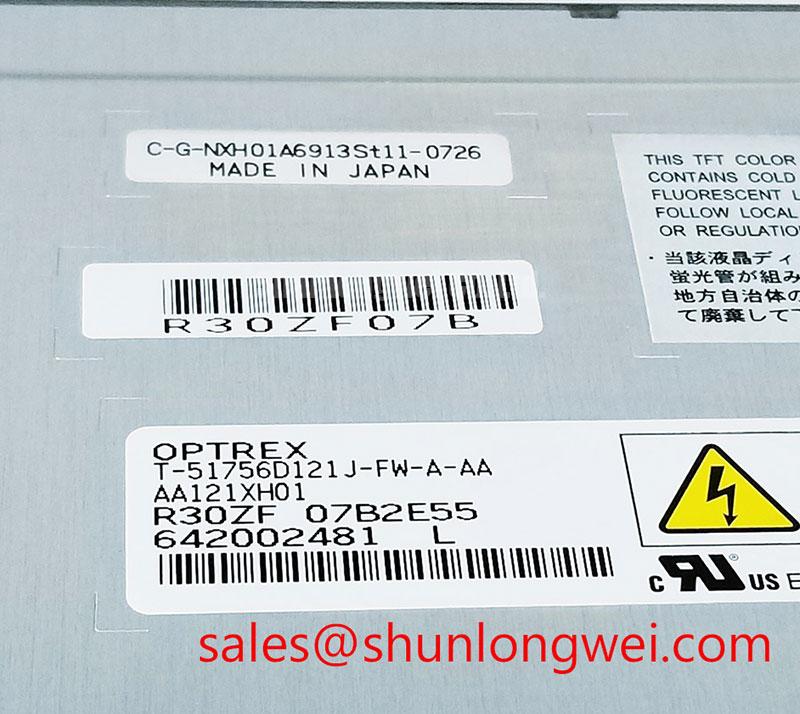
AA121XH01 Identification and Integration Check
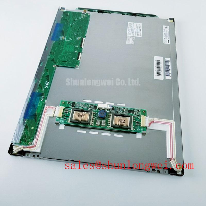
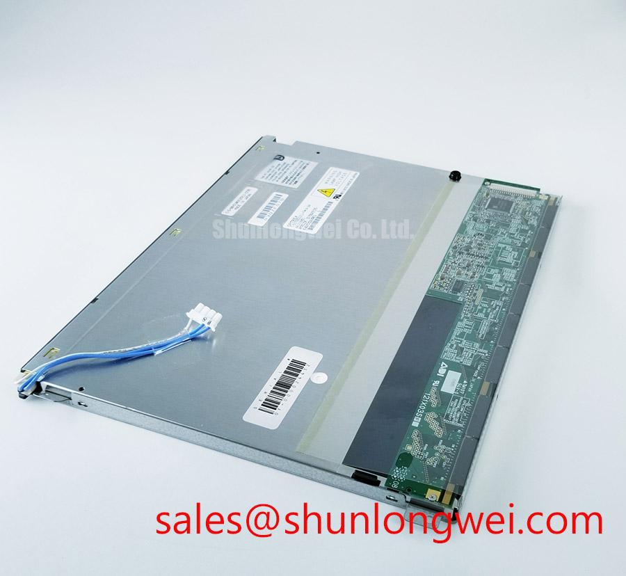
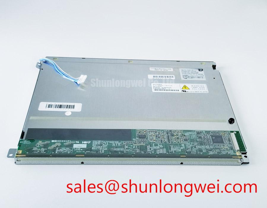
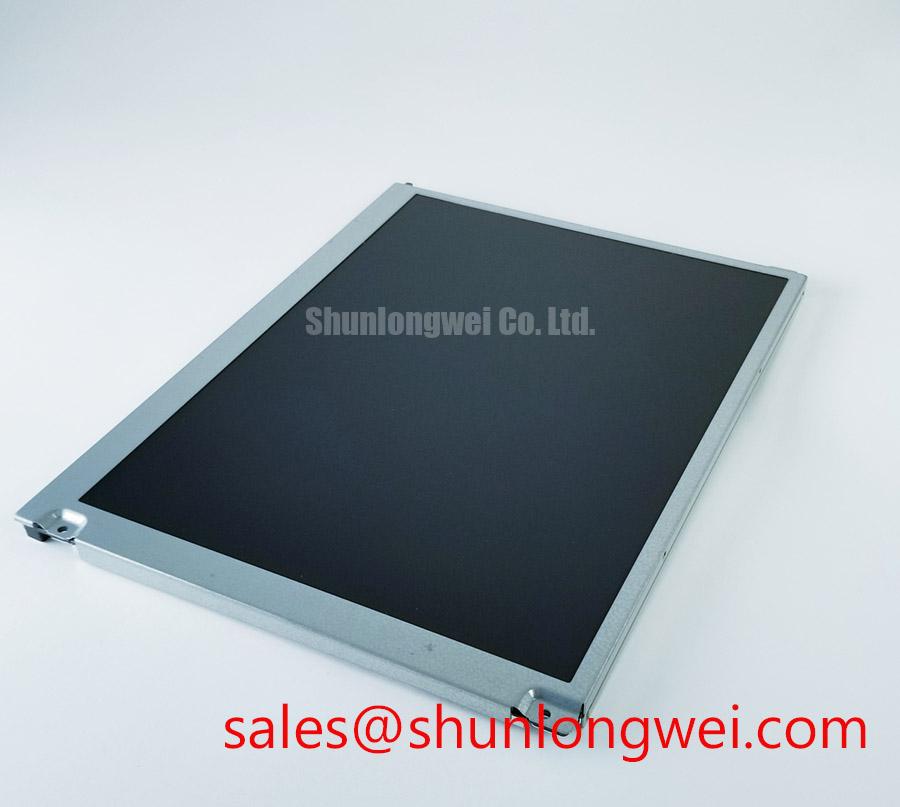
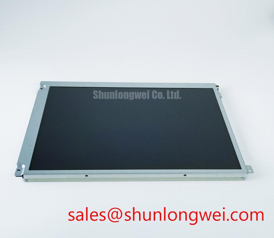
Begin the service inspection by comparing the installed panel marking with AA121XH01, then check the connector condition, bezel seating, display surface, and cable locking mechanism before applying power. The available factory information identifies this unit as a Mitsubishi Electric Industrial Grade LCD/HMI Panel in a TFT-LCD Display Module package. Its specification status is recorded as Official Factory Spec Verified. No unverified resolution, luminance, viewing angle, supply voltage, backlight type, or dimensional value should be added to a replacement decision unless it is confirmed against the original panel documentation.
For a CNC operator panel or robot teach pendant, mechanical interchangeability is only one part of the assessment. The service engineer should compare the active display area, mounting aperture, bezel depth, connector position, cable exit direction, controller interface, and backlight control method with the panel being removed. A visually similar industrial LCD can still fail to operate correctly if its LVDS mapping, timing, power sequence, or connector keying differs.
| Item | Verified information |
| Model | AA121XH01 |
| Manufacturer | Mitsubishi Electric |
| Product category | Industrial Grade LCD/HMI Panel |
| Package or housing description | TFT-LCD Display Module |
| Specification status | Official Factory Spec Verified |
When reviewing a same-size or same-resolution candidate, the neutral engineering reference AA104VC01 may assist with comparison, but it should not be treated as a drop-in substitute without confirming the complete electrical and mechanical interface. The system integrator should verify the required supply voltage from the original panel documentation rather than assuming a common industrial display voltage.
Optical bonding, perimeter sealing, anti-glare treatment, and protective cover construction should also be confirmed from the actual assembly drawing. These features affect dust ingress, condensation behavior, touch-panel compatibility, and the visibility of surface defects. They should not be inferred from the TFT-LCD category alone.
20-Pin/30-Pin Differential LVDS Timing, Pixel Clock and Skew Compensation
Before connecting an AA121XH01 replacement, identify the exact connector family and pin assignment from the source equipment documentation. The description of a 20-pin or 30-pin interface is an integration checkpoint, not a confirmed AA121XH01 product specification. The cable count, connector orientation, signal polarity, and data mapping must be matched to the original display assembly.
Design Consideration: the host board should be checked for the correct logic supply, power-on rise behavior, enable signals, pixel clock, and LVDS data format. The supplied engineering review range of 3.3 V or 5.0 V must be treated as a system-side verification item, not as an AA121XH01 rating. The same applies to the suggested power-rise inspection window of 0.5 ms to 10 ms; it may be useful when examining the host controller sequence, but it does not replace the original panel timing specification.
With the panel disconnected, inspect the cable for crushed insulation, contamination, lifted contacts, or an incompletely engaged lock. After reconnection, use the known-good signal path as the reference when checking clock activity and differential pair behavior. Split-screen images, unstable vertical regions, missing color groups, or a completely white display can have several possible sources, including mapping mismatch, missing enable control, supply sequencing, cable contact quality, or controller failure. An oscilloscope measurement at the host connector can help distinguish a missing signal from a panel-side response issue.
The suggested 100-ohm differential characteristic impedance and controlled pair routing belong to the host PCB and cable design. They should be treated as Design Considerations for signal integrity. Pair continuity, polarity, termination behavior, and propagation skew should be verified against the system design rather than assumed from the display model name. JEIDA or VESA mapping must also be confirmed from the original documentation, since incorrect mapping can produce color errors or displaced image data without indicating a damaged LCD cell.
Backlight control requires the same discipline. If the controller uses PWM, the proposed 200 Hz to 1 kHz inspection range is a bench evaluation reference for flicker, audible behavior, and duty-cycle response. It is not an official AA121XH01 backlight specification in the information provided here. Designers should confirm whether the host expects PWM, analog dimming, an enable input, or another control arrangement before connecting the module.
Evaluating Grayscale Inversion and Viewing Direction Alignment
The panel technology, optical stack, and viewing-angle performance of AA121XH01 should be confirmed from the original Mitsubishi Electric data for the exact revision. The available factory description identifies a TFT-LCD module but does not establish TN, IPS, or MVA construction, nor does it provide a certified viewing cone. Those characteristics should not be inferred from the model number.
If the source documentation identifies a normally white TN panel, the display should be evaluated from the operator’s actual position rather than from a perpendicular laboratory view alone. TN displays can show contrast changes or grayscale inversion when viewed away from the intended direction. For a CNC operator panel, the mounting angle, operator eye height, protective window, and ambient illumination can all change the perceived result. The correct response is to align the display with the machine interface geometry and confirm critical alarms, numeric values, and status colors at the expected viewing position.
The proposed 85°/85°/85°/85° viewing-angle notation must be treated as a comparison target for an alternative display, not as an official AA121XH01 value. A symmetric viewing-cone figure associated with an IPS or MVA panel should not be transferred to this Mitsubishi Electric module without a matching datasheet. Surface anti-glare treatment also requires physical confirmation. An etched or coated surface can reduce reflections in a brightly lit plant, yet excessive diffusion may soften small text or lower perceived contrast.
During commissioning, compare the replacement against a known-good image using grayscale ramps, fine text, single-pixel lines, and large uniform fields. Check the panel at the normal operating angle and at the practical upper and lower positions used by the operator. If grayscale steps change unexpectedly, inspect the source timing, data mapping, clock stability, and panel supply before attributing the behavior to the LCD technology.
TTL or LVDS transmitter clock jitter and data hold timing should be checked across the host equipment’s specified temperature range. These are interface-level engineering concerns rather than confirmed AA121XH01 specifications. A stable display at room temperature does not by itself prove timing margin at the enclosure temperature extremes. When the image becomes unstable only after warm-up or cooling, record the supply behavior and signal waveform at the failure point and compare it with the original working assembly.
Long-term static screens on HMI equipment should be managed through the application software where practical. Periodic screen changes, reduced static brightness, and appropriate idle behavior may help limit visible image retention, but the effectiveness depends on panel construction, drive conditions, temperature, and operating history. No specific burn-in lifetime or retention guarantee should be assigned without a manufacturer source.
Suppressing Pixel Jitter and Horizontal White Lines Near 400 V Motor Drives
When an operator panel is installed beside a variable-frequency motor drive, first separate the display signal cable from motor output conductors and switching nodes during a controlled inspection. Pixel jitter, horizontal bands, or intermittent white lines may involve cable coupling, grounding, common-mode disturbance, connector contact, host timing, or power-rail interference. The symptom alone does not identify one definitive cause.
Design Consideration: a shielded LVDS or FFC route should maintain a deliberate return path and avoid unnecessary loops, with the final grounding arrangement determined by the equipment’s protective-earth and signal-ground architecture. A 360-degree shield termination may be considered where the cable and enclosure design support it, but it should be validated for ground-current behavior rather than applied as an automatic repair.
The suggested 100 ohms ±10 percent differential impedance and a 50 ps or lower skew budget are system-level signal-integrity targets supplied for engineering review. They are not confirmed factory ratings for AA121XH01. The PCB designer should control pair geometry, reference-plane continuity, connector transitions, and length matching, then verify the result with appropriate measurement equipment.
Common-mode ferrite suppression can be evaluated when conducted or radiated interference remains after cable routing and grounding have been checked. The ferrite selection must account for the differential signal bandwidth, common-mode impedance, temperature, and mechanical location. An unsuitable component can reduce signal margin or alter edge behavior. Any change should be tested with the panel displaying fast-moving graphics, fine text, and uniform color fields while the adjacent drive operates through its normal switching range.
Power integrity deserves equal attention. Measure the display supply at the panel connector during drive acceleration, deceleration, and braking events, while also checking the host ground reference and backlight enable line. If the disturbance appears only during a motor transition, compare the waveform with the display cable disconnected and then connected. This approach helps distinguish a panel-interface problem from a cabinet-level coupling issue without assigning an unsupported failure threshold.
⚠️ Maintenance Note: inspect the cabinet air path, cable shield termination, connector locks, and display sealing surfaces during scheduled service, especially where vibration or dust can gradually reduce contact and enclosure integrity.
For a wider explanation of industrial TFT interface behavior, environmental design, and common display integration assumptions, consult The Ultimate Guide to Industrial TFT-LCD Technology. The guide can support system review, while the original Mitsubishi Electric documentation remains the controlling source for AA121XH01 electrical and optical limits.
Preventing Frame Lag and Image Smearing in Cold Industrial Facilities
Cold-start testing should be performed gradually, with the panel, controller, cable assembly, and enclosure exposed to the same conditions expected in service. The available information does not confirm an AA121XH01 operating-temperature rating, gray-to-gray response time, heater requirement, or sealant construction. The supplied range of −30 °C to +85 °C should therefore be treated as an environmental evaluation scenario, not as a product guarantee.
Liquid-crystal response can change as temperature falls, and visible image trailing may become more noticeable during rapid graphics transitions. Before diagnosing the LCD module, verify that the host controller continues to provide stable timing, that the backlight enable remains active, and that condensation is not present around the bezel, connector, or cable entry. The enclosure should allow moisture to equalize in a controlled manner while preventing direct exposure to dust, coolant mist, and washdown residue where applicable.
If a heater strip is included in the equipment design, its control must be determined by the system engineer from the enclosure thermal profile and the panel manufacturer’s requirements. Do not connect a heater directly to the display module unless the original assembly documentation specifies the interface and operating sequence. The warm-up process should be observed for image uniformity, response recovery, connector stability, and any change in perimeter sealing.
Mechanical stress can become more visible during temperature cycling. The mounting frame should support the display evenly, without forcing the glass, bezel, or flexible cable into a twisted position. The FPC should follow the original bend path, retain adequate strain relief, and remain clear of sharp edges. Repeated service access should not transfer pulling force to the connector contacts. If the original unit uses an optical bonding layer, gasket, protective cover, or touch overlay, each mating surface should be checked for compression uniformity and contamination before reassembly; the presence and construction of those features must be verified from the actual assembly documentation.
For CNC operator panels and robot teach pendants, validate the screen after cold soak, warm-up, vibration exposure, and repeated power cycling. Record the displayed image, touch response if fitted, backlight behavior, and connector condition at each stage. A delayed image or residual frame may involve temperature-dependent panel behavior, controller refresh timing, power sequencing, or signal integrity. Comparing the replacement with the removed known-good signal path provides a more reliable service decision than assigning the symptom to one internal mechanism.