

Content last revised on May 25, 2026
Sharp LQ150X1LG92: A Robust 15.0-Inch XGA Display for Industrial Applications
Engineering Insights into the LQ150X1LG92 TFT-LCD Module
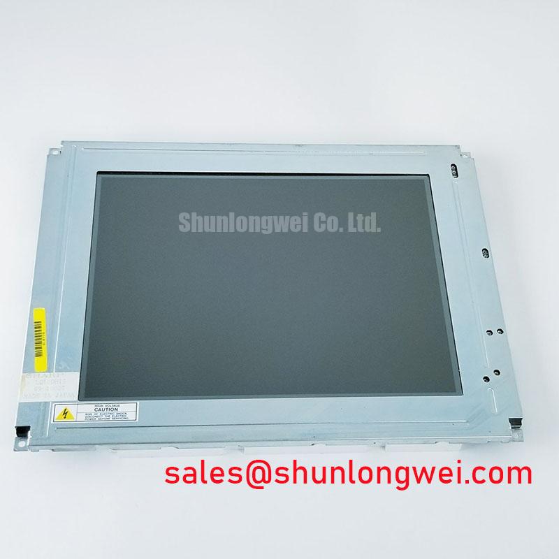
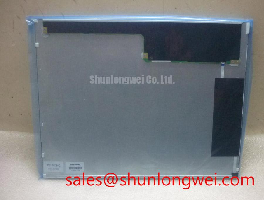
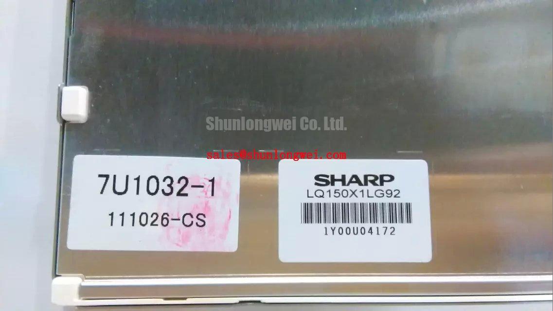
The Sharp LQ150X1LG92 is a 15.0-inch XGA display engineered for exceptional durability and visual performance in demanding operational settings. Delivering a precise 1024x768 resolution, 450 nits of brightness, and a 50,000-hour backlight lifetime, this TFT-LCD module provides both clarity and longevity. Its key benefits include sustained performance across a wide temperature range and excellent readability thanks to its anti-glare surface. This module directly addresses the need for a reliable display solution that can withstand the rigors of industrial environments without compromising on image quality. For industrial systems requiring consistent, long-term operational stability, the LQ150X1LG92's robust thermal and mechanical design makes it a premier choice.
Application Scenarios & Value
System-Level Benefits in Demanding HMI and Control Systems
The design of the Sharp LQ150X1LG92 provides tangible advantages in applications where environmental conditions are a primary engineering challenge. Consider a Human-Machine Interface (HMI) integrated into a manufacturing line's main control cabinet. This environment often lacks precise climate control, experiencing significant temperature shifts between day and night operations. The LQ150X1LG92's wide operating temperature range of -10°C to 70°C ensures consistent, flicker-free performance, preventing costly downtime caused by display failure in cold starts or high-heat conditions. What is the benefit of its 50,000-hour WLED backlight? It translates to a service life of over 5.7 years of continuous 24/7 operation, drastically reducing maintenance cycles and total cost of ownership compared to older CCFL technologies. The anti-glare surface is critical in these settings, mitigating reflections from overhead factory lighting and allowing operators to read critical data from a wide range of angles without visual fatigue. This combination of thermal resilience and optical clarity makes it a highly effective solution for industrial automation, medical diagnostic equipment, and point-of-sale terminals where reliability is paramount.
While the LQ150X1LG92 is an excellent fit for a wide array of applications, for systems demanding even higher brightness or specialized interface requirements, exploring other models may be beneficial. For example, the G150XNE-L01 offers a comparable size and resolution but features different optical characteristics that may be suited for specific use cases.
Key Parameter Overview
A Functionally Grouped Breakdown of Core Specifications
The technical specifications of the Sharp LQ150X1LG92 are tailored for straightforward integration and reliable performance. The parameters are organized below by engineering function to facilitate a clear evaluation for your system design.
| Display Characteristics | |
|---|---|
| Screen Size | 15.0 inch |
| Resolution | 1024(RGB)×768 [XGA] |
| Panel Technology | a-Si TFT-LCD, Liquid Crystal |
| Active Area (mm) | 304.128 × 228.096 |
| Outline (mm) | 326.5 × 253.5 × 12.0 |
| Optical Performance | |
| Luminance | 450 cd/m² (Typ.) |
| Contrast Ratio | 600:1 (Typ.) |
| Viewing Angle | 80/80/60/80 (Typ.)(CR≥10) (L/R/U/D) |
| Surface Treatment | Anti-glare, Hard coating (3H) |
| Interface & Environmental Ratings | |
| Signal Interface | LVDS (1 ch, 6-bit), 20 pins |
| Backlight System | WLED, 50,000 hours (Typ.) |
| Operating Temperature | -10 ~ 70 °C |
| Storage Temperature | -30 ~ 70 °C |
Download the LQ150X1LG92 datasheet for detailed specifications and performance curves.
Industry Insights & Strategic Advantage
Meeting the Reliability Demands of Modern Industrial Automation
In the context of industrial automation and Industry 4.0, component longevity is no longer a feature but a core requirement. Systems built around Programmable Logic Controllers (PLCs) and complex HMIs are expected to operate flawlessly for years, often in harsh conditions. The LQ150X1LG92 aligns directly with this strategic need. Its 600:1 contrast ratio is a key performance metric; think of it as the display's ability to distinguish between the darkest black and the brightest white. A higher ratio means sharper, more defined text and graphics, which is critical for reducing operator error when reading complex schematics or process data on an HMI screen. This level of clarity, combined with the panel's robust environmental ratings, ensures that the display is not the weak link in a mission-critical control system. What is the practical benefit of its viewing angle? A wide viewing angle ensures that multiple operators can view the screen from different positions without color distortion, crucial for collaborative environments on the factory floor.
Frequently Asked Questions (FAQ)
How does the specified 50,000-hour backlight lifetime of the LQ150X1LG92 impact the total cost of ownership (TCO)?
The 50,000-hour rating on the WLED backlight system is a critical factor in lowering TCO. It directly translates to a calculated mean time between failures (MTBF) of over 5.7 years of continuous, 24/7 operation. This significantly extends the service interval for the display, reducing the frequency of costly maintenance, technician labor, and potential system downtime associated with backlight replacement in industrial or commercial equipment.
What design considerations does the standard LVDS interface of the LQ150X1LG92 simplify for system integrators?
The use of a standard 1-channel, 6-bit LVDS interface is a major advantage for system integration. This widely adopted standard ensures compatibility with a vast range of single-board computers, industrial motherboards, and dedicated display driver boards. It simplifies the electrical design by reducing the number of required data lines compared to parallel interfaces, which in turn lowers susceptibility to electromagnetic interference (EMI)—a common challenge in industrial environments. This streamlines development and helps accelerate time-to-market.
System Integration and Support
Facilitating Your Design-In Process
To support the integration of the Sharp LQ150X1LG92 into your system, detailed documentation, including mechanical drawings and interface specifications, is available. Our team can provide access to these resources to help your engineering department evaluate the module's fit for your application. We encourage a thorough review of the official datasheet to ensure all performance and integration parameters align with your project's specific requirements. For further inquiries regarding this module or to explore display solutions with different specifications, please contact our technical support team.