Content last revised on October 20, 2026
Optical Luminance Degradation Curve & CCFL-to-LED Modernization Retrofit Pathways
Start optical inspection with a full-screen white field, followed by red, green, blue, black, and gray test patterns. This sequence helps separate pixel defects from uneven illumination, contamination, cable instability, or controller-side image errors. Record brightness at the center and near the perimeter using the same measurement geometry each time. A panel replacement decision should be based on the observed luminance distribution and the equipment’s visibility requirement rather than on the backlight type alone.
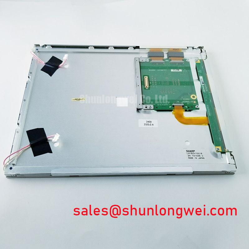
The LQ150X1LX91 baseline identifies the display module but does not specify whether a particular installed assembly uses a CCFL backlight, an LED backlight, or a retrofit arrangement. For a CCFL-to-LED modernization, the replacement driver must be evaluated as a separate subsystem. Cold ignition voltage, lamp current, LED constant-current regulation, open-load behavior, short-circuit protection, thermal derating, and dimming control all belong to the driver and backlight assembly documentation. Do not transfer a target such as a 50,000-hour half-brightness point to this Sharp panel unless it is stated for the actual fitted backlight system.
When a constant-current LED driver is considered, examine startup overshoot, current settling, thermal rise, and the relationship between PWM duty cycle and perceived brightness. A PWM range selected for a precision electronic test instrument should avoid visible modulation during camera inspection and should remain compatible with the host controller’s timing. Acoustic noise should be checked with the display mounted in its final enclosure, because mechanical resonance can make a driver or inductor appear noisy only after installation.
Clock integrity also matters during modernization. TTL and LVDS transmitters should be checked for edge quality, clock jitter, and data hold behavior across the intended operating temperature window. If the image remains stable at room temperature but becomes unstable after cold soak or enclosure heating, compare the clock and data waveforms at the panel connector rather than assuming an optical fault.
VESA vs. JEIDA Data Mapping Alignment & Even/Odd Channel Signal Integrity
Split-screen images, incorrect color groups, or a picture that appears shifted by channel often require a mapping review before panel replacement. VESA and JEIDA describe different LVDS bit arrangements, and a controller configured for the wrong convention can produce a stable but unusable image. Confirm the original panel pin assignment and controller configuration as a matched pair; do not infer the mapping from connector shape alone.
Power sequencing should be observed at the panel connector with the display disconnected and connected under controlled conditions. The system integrator should verify the required logic supply voltage from the original panel documentation rather than selecting between common nominal values by assumption. A controlled power rise, correct enable order, and clean reset release reduce the chance of a blank screen being misdiagnosed as a failed LCD cell.
For differential routing, a 100-ohm characteristic impedance is a common Design Consideration for LVDS traces, but the finished assembly must be checked against the selected transmitter, receiver, cable, connector, and board stack-up. Keep even and odd channel lengths consistent, avoid unnecessary vias, and maintain a continuous reference path. When a channel pair is routed through an FFC or FPC, the cable construction becomes part of the signal path and cannot be evaluated separately from the connector transition.
Backlight evaluation should be performed independently from data mapping. A stable image with falling luminance points toward the illumination path, while a bright but corrupted image points attention toward timing, mapping, grounding, or signal integrity. Any LED lifetime curve should be treated as an application-level test result unless the driver and backlight manufacturer provides the applicable measurement conditions. The same discipline applies to brightness maintenance claims and MTBF language.
For a same-size or same-resolution comparison, engineers may place TX18D203VM2BAA beside the LQ150X1LX91 in a compatibility worksheet, comparing connector orientation, optical area, mounting features, timing configuration, and host firmware requirements without assuming interchangeability.
Mitigating Gray-to-Gray Response Time Escalation during Cold-Start Machine Power-Up
Cold-start image lag should be evaluated with moving gray transitions rather than a static color screen. Liquid-crystal response can slow as temperature falls, while the controller, cable, and backlight driver may introduce separate startup delays. Capture the first several seconds of operation after power-up and compare a gray-to-gray test pattern with a stable warm-state image. This identifies whether the visible delay is associated with pixel transition behavior, signal initialization, or illumination startup.
The LQ150X1LX91 product identity does not publish a GTG response specification or a guaranteed thermal operating range. Engineers evaluating the panel for a wide-temperature instrument should use the original Sharp documentation and the equipment’s validated chamber profile to define the test limits. Perimeter seal condition, bezel pressure, and mounting flatness should be inspected after thermal cycling because mechanical stress can appear as localized optical nonuniformity or intermittent edge behavior.
High-EMI installations require attention to differential-pair symmetry. A 100-ohm ±10% differential target and a skew budget of 50 ps or less may be used as Design Considerations only when they match the selected interface and stack-up. The system designer should confirm the actual receiver tolerance, cable characteristics, and eye margin with measurements at the panel end. If the display is used in a CNC operator pendant, industrial HMI console, or variable-frequency-drive cabinet, enclosure temperature and cable routing should be assessed together.
The article The Ultimate Guide to Industrial TFT LCD Technology provides a useful reference for practical TFT evaluation, interface selection, and installation checks when the panel is being assessed for a replacement program.
Shielded FFC/FPC Flat Flexible Cable Grounding across 360-Degree Connector Shells
Intermittent pixel jitter and horizontal noise bands should be investigated at the flexible interconnect before the panel is condemned. Inspect the FFC or FPC for crease marks, uneven insertion, exposed contacts, and incomplete lock engagement. A connector shell or shield should be bonded according to the equipment grounding architecture, with the return path kept separate from sensitive signal references where the system design requires it.
Near a variable-frequency motor drive, cable routing should maintain practical separation from high-current switching conductors and avoid large exposed loop areas. Shield termination must be assessed at the enclosure and connector interfaces rather than relying on a shield that ends several centimeters away from the panel entry point. Common-mode filtering can be considered when measurements show conducted interference, but ferrite selection and placement remain system-design decisions; they are not stated features of the LQ150X1LX91.
For clock and data verification, probe at the receiving end with the shortest practical connection and compare the waveform against a known-good path. Check for common-mode movement, excessive ringing, irregular duty cycle, and timing changes when the cable is gently repositioned. Do not flex the cable while powered unless the equipment procedure specifically permits it.
💡 Bench Tip: Disconnect power before reseating the FFC or FPC, protect the panel and cable from ESD, and confirm that the cable is fully parallel to the connector before closing the lock.
After installation, repeat the full-screen pixel and luminance inspection with the enclosure closed, the cable dressed as it will be in service, and nearby switching equipment operating under normal conditions. This final check captures grounding, mechanical constraint, thermal behavior, and optical performance in the assembled instrument rather than only on an open bench.