Content last revised on September 6, 2026
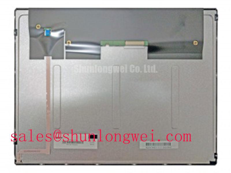
LTM15C151A Toshiba Industrial Grade LCD/HMI Panel Module
Begin a field replacement check by comparing the installed panel label with LTM15C151A, then inspect the bezel, connector area, glass surface, and mounting perimeter before applying power. This Toshiba unit is identified in the available product data as an Industrial Grade LCD/HMI Panel in a module format. The available product data does not establish a complete electrical pinout, supply voltage, interface type, backlight technology, brightness rating, contrast ratio, touch function, or environmental certification. The original equipment documentation remains the controlling reference for those values.
That distinction matters when a display is being considered for a harsh marine radar or navigation bridge console. A panel that fits the opening may still require different signal timing, power sequencing, backlight control, or mechanical support. Use the model marking as the first identity checkpoint, but confirm every system-dependent requirement against the equipment service manual and the documentation supplied with the original display assembly.
Flush-Mount Open-Frame Bezel Integration and Perimeter Gasket Shock Isolation
For a flush-mounted installation, first record the existing cutout, bezel contact points, fastener locations, gasket compression pattern, and cable exit direction. The official product information identifies the package as a Module, but it does not provide a dimensional drawing or a manufacturer-defined outer bezel tolerance in the supplied specification set. Do not machine a replacement panel opening from a visual comparison alone. Measure the installed chassis and compare it with the dimensional drawing for the exact production revision.
A perimeter gasket should distribute contact pressure around the display rather than transfer concentrated force into the glass. This is a general Design Consideration for industrial HMI integration, particularly where vibration, enclosure flex, and repeated service access are present. The gasket material, thickness, compression behavior, and environmental compatibility must be selected by the system designer. They are not factory specifications for LTM15C151A.
When cross-tightening fasteners, use the equipment manufacturer’s approved torque data. A controlled cross-pattern can reduce local frame distortion, but the supplied factory data does not state an LTM15C151A fastener size or torque limit. A value intended for another display frame must not be transferred to this model without checking the mechanical drawing. The same principle applies to bracket washers, spacers, captive nuts, and any rear support rail.
In direct sunlight, a dark display area can be mistaken for a backlight problem, surface reflection, signal loss, or optical non-uniformity. The supplied data does not confirm an anti-glare or anti-reflective coating, nor does it specify a contrast ratio at a defined illumination level. For a bridge console installation, the integrator should evaluate readable contrast at the actual viewing angle and under representative sunlight, while also checking whether the enclosure window introduces reflections.
Salt exposure creates an additional enclosure-level concern. The panel itself should not be treated as proof of marine ingress protection or salt-fog qualification. Designers should verify sealing, drainage, connector protection, and coating requirements at the complete equipment level. The wider Industrial Display & HMI Solutions reference can assist engineers reviewing display integration in demanding environments.
Micro-Twist Mechanical Stress and Glass Substrate Driver Fault Isolation
When a display arrives with a black screen, intermittent image, shadowed areas, or colored vertical lines, begin with a controlled visual and electrical inspection rather than flexing the panel. Check whether the chassis is forcing the glass into a twisted position, whether a bracket touches the active area, and whether the cable is pulling sideways on its connector. Mechanical stress can produce symptoms that resemble an electronic driver fault, but the available LTM15C151A factory information does not identify an internal driver construction or define a field diagnostic threshold.
A useful bench sequence is to display separate red, green, and blue test fields, followed by white, black, and neutral gray patterns. Observe the panel without pressing the glass or frame. A narrow flashlight held at approximately a 45-degree angle can help reveal faint image content when the backlight is absent or weak. This is a practical Design Consideration, not a Toshiba acceptance test. The result should be compared with a known-good system path whenever possible.
If the image changes when the cable is repositioned, inspect connector seating, latch engagement, contamination, cable bend radius, and mating contact alignment. Do not assume that a changing image proves a broken glass connection. Verify the source board, cable continuity, enable signals, and timing behavior in the equipment documentation. The system integrator should also confirm whether the display uses the same signal interface and pin assignment as the original assembly.
The available official data does not confirm a PWM backlight input, PWM frequency range, dimming duty-cycle characteristic, or audible-noise behavior for this model. If the host system provides brightness control, the engineer should verify the required control type and electrical levels from the original panel documentation before connecting the dimming line. A replacement backlight driver must also be assessed for startup behavior, open-load response, short-circuit protection, and fault reporting at the system level.
Touch capability is not established in the supplied product data. Do not assume that the LTM15C151A includes resistive or capacitive touch, glove operation, or wet-finger response. If the target console requires touch input, confirm the touch layer, controller interface, calibration method, and environmental performance from the original equipment records. A display image test cannot validate touch functionality.
Field Alert: Disconnect system power and follow the equipment discharge procedure before removing or inserting the display cable, because an energized interface can expose signal and power contacts to avoidable electrical stress.
Radiated Emissions Control Around Industrial Motor Drives
Pixel jitter, horizontal noise bands, unstable synchronization, or a display that recovers when a motor drive changes state should be investigated as a complete wiring and grounding problem. The LTM15C151A factory information supplied here does not define a TTL or LVDS interface, clock tolerance, data hold time, cable shielding arrangement, or independent EMC certification. The panel must therefore be evaluated within the host equipment rather than assigned a standalone CISPR Class A or Class B compliance claim.
Start by separating display signal wiring from inverter, servo, relay, and contactor conductors. Inspect the cable route for long parallel runs and unintentional coupling through cable trays or hinged doors. Shield termination should follow the equipment EMC architecture. A 360-degree shield connection may be appropriate in some high-frequency enclosure designs, but its implementation depends on connector construction, chassis bonding, cable type, and the system grounding strategy.
Star grounding is not a universal cure. A grounding point that improves one operating condition can create a circulating current path in another. Treat grounding as a Design Consideration: establish a controlled reference for the display electronics, minimize high-current return sharing, and verify the result during switching tests with the complete enclosure assembled. The engineer should inspect both the display end and controller end of the cable, including shield clamps, backshells, strain relief, and paint or anodizing at bonding surfaces.
Common-mode ferrite components may reduce coupled interference when their impedance and current capability suit the cable and signal spectrum. They should not be added as an automatic replacement for correct routing, termination, or shield bonding. If a ferrite is evaluated, compare the display waveform before and after installation with an oscilloscope or suitable EMC test setup. Check the signal at the receiver under the same motor-drive operating conditions that produce the visible fault.
Because the available specification does not state the interface standard, do not apply a presumed differential-pair impedance, skew budget, clock rate, or termination value to this specific model. Obtain the panel interface documentation first. Then verify signal amplitude, common-mode range, edge quality, setup and hold behavior, and timing margin over the equipment’s operating temperature range. Any corrective value must come from the interface design and measured system behavior.
For a marine bridge console, radar processor, navigation computer, and display enclosure should be tested as one installation. The panel’s official category and module construction do not independently demonstrate immunity, emissions compliance, or salt-environment reliability for the finished console. System-level verification remains necessary after cable routing, shielding, grounding, and enclosure changes.
Heat Spreader Placement Along Narrow Display Edges
Thermal inspection should begin with the actual panel operating in its installed enclosure. Record the location of warm regions on the rear frame, controller board area, backlight driver area, and nearby power conversion hardware. The official data supplied for LTM15C151A does not specify power consumption, allowable case temperature, thermal resistance, backlight lifetime, LED operating hours, or an L70 or B50 value. Those figures must not be inferred from the model name or from another Toshiba display.
An aluminum spreader rail can be considered when heat is concentrated near a narrow edge, but it must not obstruct vents, press against the rear electronics, or create a mechanical load on the glass. The rail profile, attachment method, thermal interface material, and chassis bonding are system design choices. The engineer should confirm that the proposed spreader does not interfere with insulation distances, cable movement, service access, or the original heat path.
Thermal interface material should be applied only where the mechanical drawing and assembly method provide a defined contact surface. Excessive material can shift a frame, contaminate connectors, or create uneven pressure. A metal rail attached to a painted enclosure may also behave differently from one bonded directly to a prepared chassis surface. Validate contact uniformity and temperature distribution after the display has reached its representative operating condition.
Backlight symptoms require separation of electrical, optical, and thermal checks. A dark screen with visible image content may point the investigation toward the backlight circuit, while a completely absent image requires signal and power checks as well. These observations are screening clues rather than conclusive diagnoses. Verify the supply path, enable behavior, protection response, connector condition, and source waveform against the original equipment documentation.
Do not advertise a specific MTBF or long-term brightness-retention figure for this unit unless it appears in the applicable Toshiba factory document for the exact revision. A stated operating life from a different panel, a replacement backlight assembly, or a separate driver cannot be transferred automatically. For procurement and repair records, retain the model marking, revision information, dimensional confirmation, interface documentation, and test results from the completed equipment.
Before approving installation, the system integrator should verify the required supply voltage, signal interface, backlight control method, touch requirements, mounting geometry, environmental protection, and thermal limits from the original panel documentation. This Toshiba LTM15C151A is identified here as an industrial grade LCD/HMI panel module; all additional operating boundaries must be confirmed for the target console.