Content last revised on September 24, 2026
Assembly Integrity & Layout Architecture: RC Snubber Network Optimization for M50100TB1600-8699
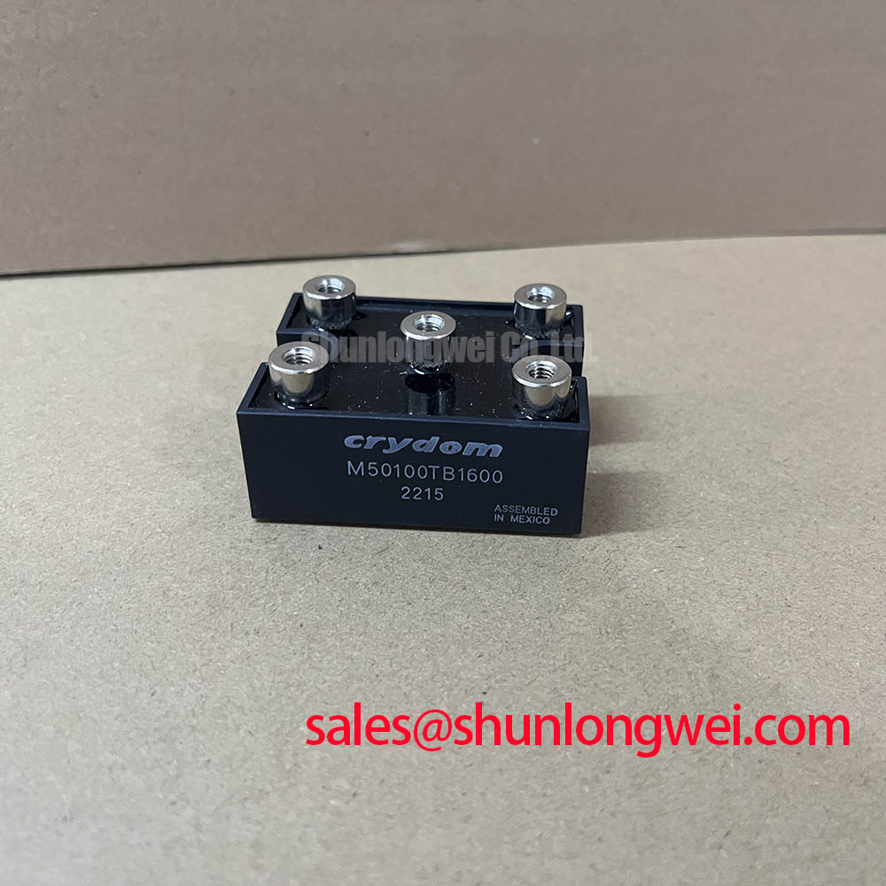
Begin incoming inspection with the module disconnected from every circuit: check the case for visible damage, confirm the nameplate identity, and record the cold-state terminal measurements before applying any operating voltage. The supplied factory data identifies the M50100TB1600-8699 as a SanRex / Crydom isolated power module with a rated voltage of 1600.0 V and a rated current of 10.0 A. Its product category is listed as a Diode/Thyristor Module. These are official supplied specifications; fuse coordination, switching limits, thermal resistance, terminal layout, and mounting torque should be confirmed against the applicable manufacturer documentation before replacement.
| Parameter | Specified value |
| Manufacturer | SanRex / Crydom |
| Model | M50100TB1600-8699 |
| Rated voltage | 1600.0 V |
| Rated current | 10.0 A |
| Housing | Isolated Power Module |
For a grid tied static Var compensator or thyristor switched capacitor assembly, inspect the complete commutation path rather than evaluating the power module in isolation. The snubber resistor and capacitor, any series saturable reactor, semiconductor fuse, busbar, and terminal connections form one switching loop. An Engineering Recommendation is to minimize parasitic loop inductance and keep the snubber connection physically close to the relevant power terminals. The final Rs and Cs values remain system determined and should be validated during switching tests for voltage overshoot, dv/dt induced triggering, and thermal loading.
Do not infer the permissible fuse I2t coordination from the 10.0 A rating alone. The engineer responsible for the installation should compare the selected semiconductor fuse characteristic with the applicable module protection table and prospective fault current. Terminal polarity and phase assignment must be checked against the original assembly drawing. The M505013F may be reviewed as a separate same-family selection reference, but electrical interchangeability must be established by the system designer.
M50100TB1600-8699 Operational Boundaries: Evaluating Commutation Turn-Off Voltage Spikes
When examining turn-off behavior, capture the commutation waveform at the module terminals with an appropriately rated differential probe and compare it with a known-good assembly. Reverse-recovery current, recovery time, damping, and the resulting voltage excursion depend on the circuit current, source impedance, stray inductance, gate or control timing where applicable, and the external snubber network. The supplied product data confirms the 1600.0 V voltage class, but it does not by itself establish a universal switching frequency, dv/dt limit, Irrm, or trr value for every operating condition.
For a thyristor-switched capacitor branch, review the firing sequence, capacitor precharge condition, reactor behavior, and fuse response together. System engineers should verify peak terminal voltage against the actual DC-link or AC commutation environment rather than treating the nameplate voltage as a target operating point. The industrial-drive discussion in Unlocking Efficiency in Industrial Drives can provide broader switching-layout context, although it does not replace the product-specific documentation for this module.
Preventing Spurious Faults: Ensuring Uniform Heatsink Contact Pressure Guidelines for M50100TB1600-8699
The isolated power module should be mounted on a clean, flat heatsink surface with an even thermal interface. Excess compound, uneven fastener loading, contamination, or a distorted base can create local thermal gradients and mechanical stress. Because the supplied parameter set does not provide Rth(j-c), baseplate dimensions, or a factory mounting torque, those values should be taken from the correct mechanical drawing and datasheet revision rather than estimated from similar packages.
After installation, inspect the clamping arrangement, conductor clearance, insulation spacing, and terminal tightness as part of the same acceptance record. A thermal camera or temperature sensor can help compare phase positions during a controlled low-energy test, but measured temperature should be interpreted with airflow, heatsink condition, current sharing, and switching duty in mind. For assemblies using ceramic substrate technology, automated X-ray inspection is a relevant industry method for examining solder void distribution where the assembly process calls for it.
💡 Bench Tip: Use ESD controls and compare cold-state diode or thyristor terminal readings with an approved known-good reference before connecting the module to the energized circuit.
M50100TB1600-8699 Thermal-Electrical Optimization: Power Factor and Harmonic Mitigation
In an SVC or thyristor-switched capacitor installation, firing-angle changes affect conduction interval, reactive power exchange, line current waveform, and semiconductor heating. The requested 0 degree to 150 degree firing-angle range should be treated as a system study boundary, not as a guaranteed operating range for the M50100TB1600-8699. Designers should measure phase voltage, phase current, displacement power factor, harmonic content, and module temperature across the intended control sequence.
Check the controller feedback path, current-transformer polarity, synchronization reference, and gate or trigger isolation before attributing poor power factor to the module. Isolated current-sensing circuits may use conversion methods such as Delta-Sigma modulation, but the selected sensing interface must be verified from the actual control-board documentation. In high-current battery or DC conversion equipment, the same inspection discipline applies to busbar overlap, turn-off overshoot, cooling contact, and repeated thermal cycling; the module’s suitability remains dependent on measured system stress and documented ratings.