


Content last revised on May 14, 2026
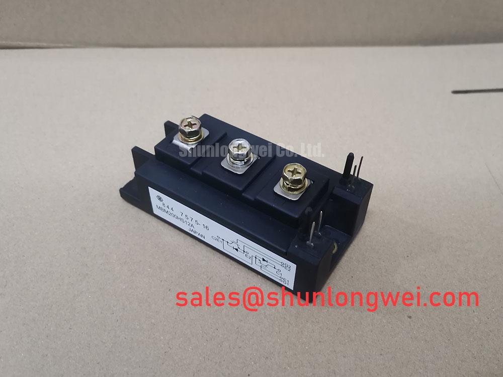
MBM200HS12A: A Robust 1200V Half-Bridge IGBT Module for High-Reliability Power Conversion
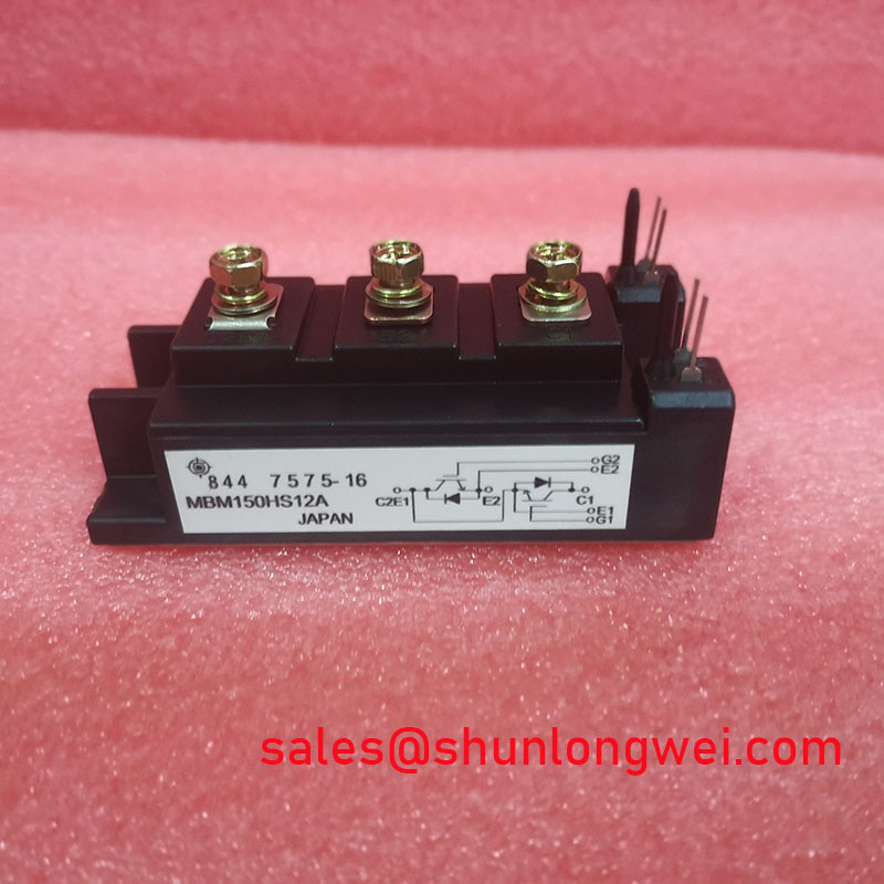
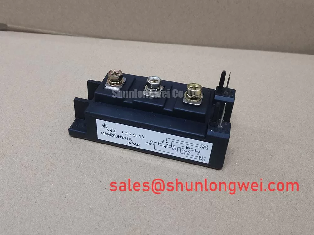
The Hitachi MBM200HS12A is a high-performance IGBT module engineered for demanding power conversion applications, delivering robust performance through a combination of high voltage and current ratings. This module integrates two IGBTs in a half-bridge configuration, providing a foundational building block for various inverter and converter topologies. Its specifications are tailored to balance switching efficiency and conduction performance, making it a strategic component for systems where reliability and thermal stability are critical design parameters.
Application Scenarios & Value
Achieving Robust Performance in Industrial Motor Drives and Power Supplies
The MBM200HS12A is engineered to excel in high-power industrial applications such as Variable Frequency Drives (VFDs), uninterruptible power supplies (UPS), and industrial welding systems. For a design engineer developing a 100 kW VFD, the primary challenge is managing thermal losses while ensuring the drive can withstand the harsh electrical environment. The MBM200HS12A's 1200V collector-emitter voltage (Vces) provides a substantial safety margin for systems operating on 400V or 480V AC lines, effectively handling voltage transients and improving long-term reliability. Its 200A continuous collector current rating (Ic) ensures it can manage the power throughput required for medium- to high-power motors without approaching its operational limits. This robust electrical specification simplifies the design of the power stage, allowing engineers to focus on control logic and system integration. For systems demanding higher power handling, the related CM400HA-24H offers a higher current capability for scaling designs.
Key Parameter Overview
Defining Electrical and Thermal Performance
The technical specifications of the MBM200HS12A underscore its suitability for high-reliability power systems. The module's performance is characterized by its voltage and current ratings, thermal impedance, and switching characteristics. These parameters are crucial for accurate system modeling, thermal management design, and performance prediction.
| Parameter | Symbol | Value | Unit | Conditions |
|---|---|---|---|---|
| Absolute Maximum Ratings (at Tc=25°C) | ||||
| Collector-Emitter Voltage | Vces | 1200 | V | Vge=0V |
| Gate-Emitter Voltage | Vges | ±20 | V | |
| Collector Current (DC) | Ic | 200 | A | Tc=80°C |
| Collector Current (Pulsed) | Icp | 400 | A | 1ms pulse |
| Collector Power Dissipation | Pc | 1380 | W | Per IGBT |
| Operating Junction Temperature | Tj | +150 | °C | |
| Electrical Characteristics (at Tj=25°C unless otherwise noted) | ||||
| Collector-Emitter Saturation Voltage | VCE(sat) | 2.7 (Typ) / 3.4 (Max) | V | Ic=200A, Vge=15V |
| Gate Threshold Voltage | VGE(th) | 5.0 to 8.0 | V | Ic=200mA, Vce=10V |
| Collector Cut-off Current | Ices | 1.0 | mA | Vce=1200V, Vge=0V |
| Thermal Characteristics | ||||
| Thermal Resistance, Junction-to-Case | Rth(j-c) | 0.09 | °C/W | Per IGBT |
Frequently Asked Questions (FAQ)
What is the primary implication of the 3.4V maximum VCE(sat) for system design?
The collector-emitter saturation voltage, VCE(sat), is a critical parameter that dictates conduction losses. A maximum value of 3.4V at the rated current of 200A means that during the 'on' state, the power dissipated as heat per IGBT can be calculated (P = VCE(sat) * Ic). Engineers must factor this into their thermal management strategy. This value represents a trade-off between conduction losses and the device's switching speed and voltage blocking capability. For designers, this means selecting an appropriate heatsink to maintain the junction temperature well below the 150°C maximum, ensuring both performance and long-term reliability.
How does the half-bridge (2-in-1) configuration of the MBM200HS12A benefit inverter design?
The half-bridge configuration significantly simplifies the layout of single-phase and three-phase inverters. By integrating two IGBTs in a standard phase-leg topology, it reduces the component count and minimizes stray inductance between the high-side and low-side switches. This optimized internal layout leads to cleaner switching waveforms, reduced voltage overshoot, and improved electromagnetic compatibility (EMC) performance, which are critical considerations in modern high-efficiency power systems.
What is the significance of the specified thermal resistance, Rth(j-c)?
The junction-to-case thermal resistance (Rth(j-c)) of 0.09 °C/W is a direct measure of how efficiently heat can be transferred from the active semiconductor junction to the module's baseplate. A lower Rth(j-c) value is always better. Think of it as the width of a pipe for heat to escape—a wider pipe (lower resistance) allows more heat to flow out easily. This specific value allows engineers to precisely calculate the junction temperature based on power dissipation, enabling the design of a more compact and cost-effective cooling system while maintaining a safe operating temperature for the device.
Technical Deep Dive
Interpreting VCE(sat) and Rth(j-c) for System-Level Thermal Management
A deeper analysis of the MBM200HS12A's key parameters reveals a focus on thermal robustness. The maximum collector-emitter saturation voltage (VCE(sat)) of 3.4V at 200A and a junction temperature of 125°C is a pivotal data point. This value directly informs the calculation of conduction losses, which are often the dominant source of heat in high-current, lower-frequency applications like motor drives. It's the equivalent of electrical friction; a lower number means less energy is wasted as heat when the switch is fully on.
This links directly to the thermal resistance from junction to case (Rth(j-c)) of 0.09 °C/W. This parameter quantifies the module's intrinsic ability to evacuate heat from the silicon chip to the heatsink mounting surface. Combining these two specifications, a system designer can build a precise thermal model. For example, at a continuous 200A operation, the conduction loss per IGBT is significant, and the Rth(j-c) value dictates the temperature rise at the junction. Effective thermal management is thus not just about adding a large heatsink, but about leveraging the module's specified performance to create an optimized and reliable cooling solution.
Industry Insights & Strategic Advantage
Meeting Reliability Demands in Mature Industrial Infrastructure
The MBM200HS12A is a component well-suited for the backbone of industrial automation: the AC motor drive. In an era focused on energy efficiency and system longevity, the reliability of power electronics is paramount. This module's standard package and robust electrical characteristics align with the industry's need for proven, dependable components for both new systems and the maintenance of an extensive installed base. As industrial machinery is expected to operate for decades, the use of well-characterized modules like the MBM200HS12A ensures long-term serviceability. Its design provides the ruggedness needed to withstand the electrical and thermal stresses inherent in factory environments, from conveyor systems to HVAC applications, supporting the broader goals of uninterrupted production and reduced total cost of ownership.
To further explore the foundational principles of IGBT technology and its applications, consider our in-depth article on deconstructing the IGBT's structure and technology.
For a comprehensive technical overview of various power semiconductor technologies, Hitachi Energy provides a broad portfolio of high-power devices.
Request for Quotation
To inquire about the MBM200HS12A for your application, please contact our sales team for pricing and availability information. Our specialists are available to support your engineering and procurement requirements.