
Content last revised on September 20, 2026
MCC26-16IO1B Circuit Protection & Reliability: Calibrating IEEE 61000-4-5 Industrial Surge Immunity
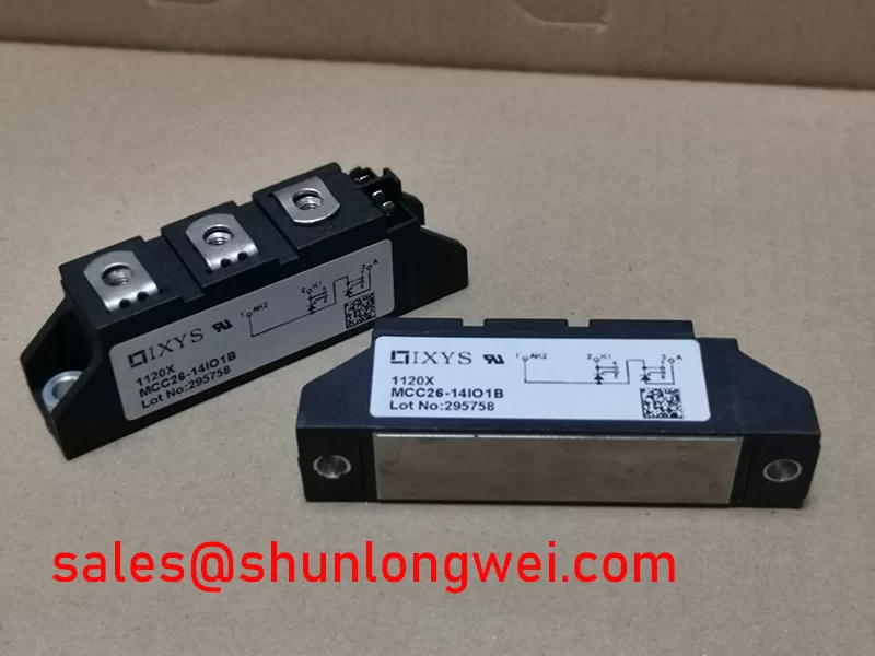
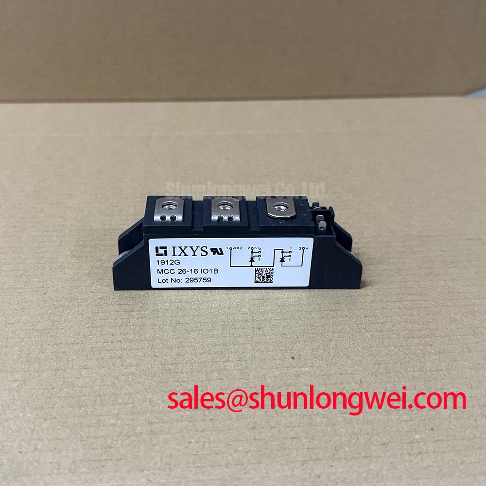
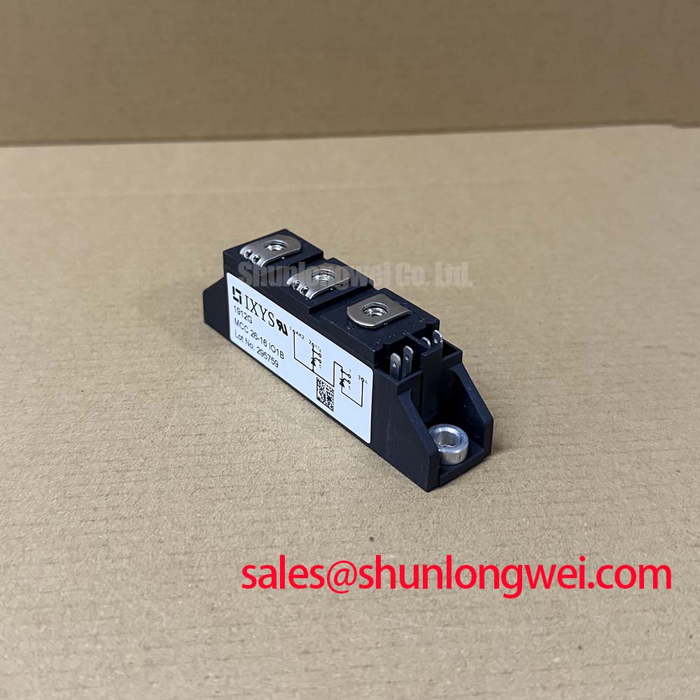
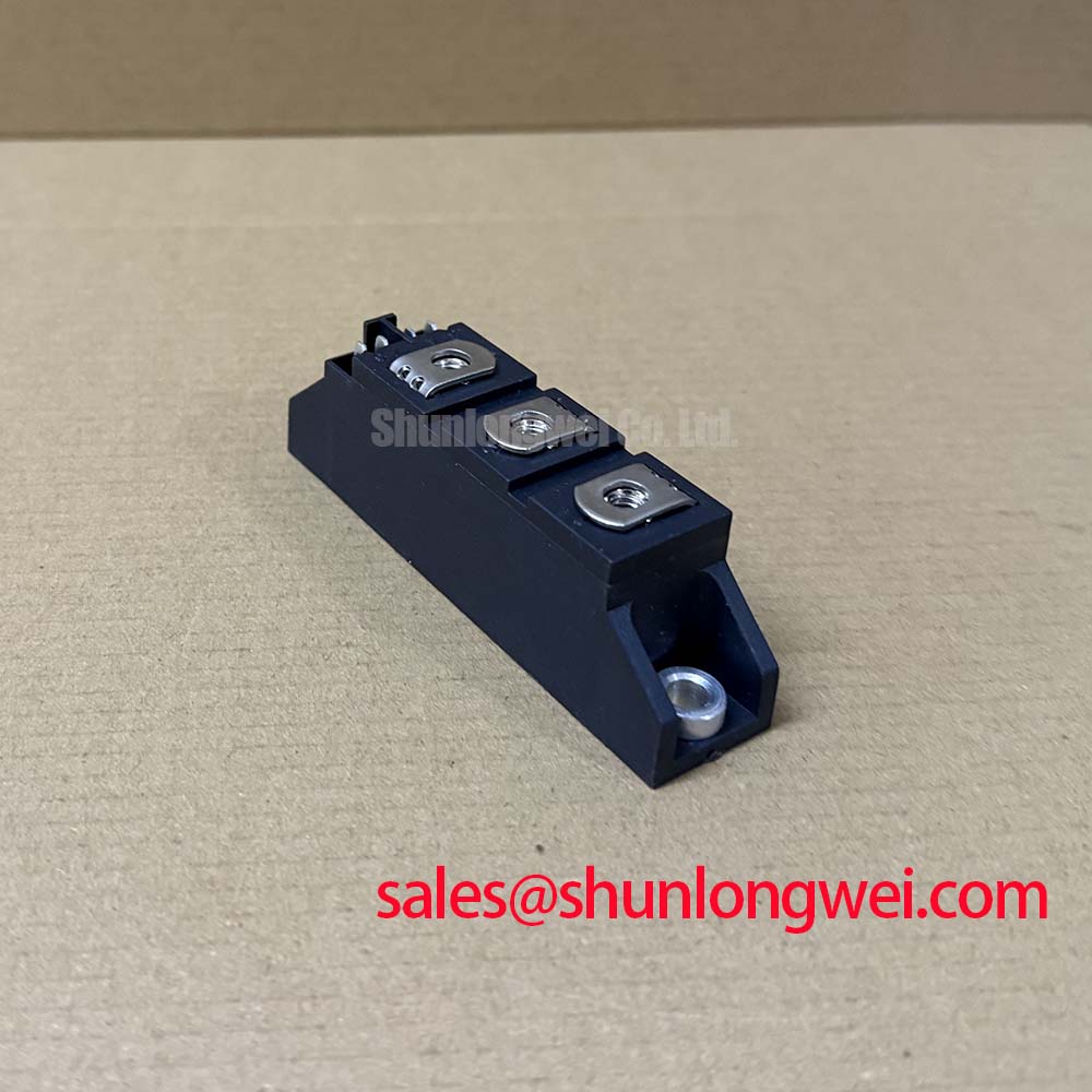
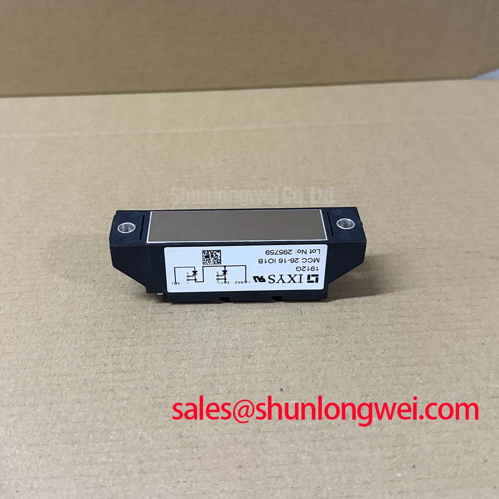
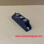
With the equipment isolated and discharged, verify the device marking and compare the installed electrical boundary with the MCC26-16IO1B rating of 1600 V and 26 A before reconnecting any power or gate wiring. This IXYS dual thyristor module is supplied in a module package and should be assessed as part of its complete commutation path, semiconductor fuse arrangement, heatsink interface, and triggering circuit rather than by nominal current alone.
For repair work, record the original terminal orientation, busbar positions, gate and cathode lead routing, and protective components before removal. A cold resistance check can identify obvious unwanted conductive paths between power terminals, but it cannot establish dynamic blocking capability, latching behavior, trigger sensitivity, surge capability, or thermal integrity. Those characteristics require controlled testing against the original equipment documentation and applicable service procedure.
| Parameter | Value | Classification |
|---|---|---|
| Product model | MCC26-16IO1B | Official product identification |
| Manufacturer | IXYS | Official product identification |
| Repetitive voltage rating | 1600 V | Official Specification |
| Rated current | 26 A | Official Specification |
| Package style | Module | Official Specification |
| Device category | Dual thyristor module | Product classification |
The 1600 V rating is an Official Specification for the MCC26-16IO1B and defines an important device-level blocking boundary. It does not, by itself, establish that a complete cabinet, capacitor bank, or static var compensator assembly meets IEEE 61000-4-5 surge immunity. Surge performance is determined by the incoming supply network, upstream disconnects, cable routing, grounding arrangement, transient protection, snubber implementation, control isolation, and the actual test configuration.
In thyristor switched capacitor equipment, voltage transients can arise from switching events, contactor action, transformer coupling, capacitor bank energization, and external surge exposure. A Design Consideration is to examine whether metal oxide varistors, RC snubbers, line reactors, surge arresters, and semiconductor fuses remain electrically coordinated with the system’s measured transient environment. The clamp characteristic of a protective element must be reviewed at the relevant surge current, while its energy capability must be evaluated for the expected duty. A component that limits one transient mode can be unsuitable for repetitive events or for a sustained overvoltage condition.
The RC snubber path should be reviewed as a complete loop from the thyristor terminals through its wiring and back to the module. Its purpose is to control voltage rise conditions and ringing that may challenge the blocking device or disturb triggering behavior. The values of resistance and capacitance are system determined and should be verified through measured voltage waveforms, rather than copied from an unrelated controller. Wiring length, shared return paths, and busbar geometry can materially affect the observed result.
IEEE 61000-4-5 is an equipment-level immunity framework. It should therefore be used by system engineers to define and document an appropriate surge test plan, not as a certification statement for this individual module. When evaluating the MCC26-16IO1B in grid-connected reactive power equipment, confirm that the protective network limits terminal stress within the module’s documented voltage boundary under the operating and test conditions being assessed.
Semiconductor fuse selection also requires the full original device documentation. Fuse coordination depends on the device surge and fault withstand data, the fuse total clearing characteristic, prospective fault current, source impedance, and protection operating sequence. No numerical I²t withstand value or fuse coordination table is stated here because it is not among the supplied official specifications. A service engineer should obtain the applicable IXYS data and the equipment fuse documentation before approving a replacement arrangement.
💡 Pro Tip: Keep the main current busbars mechanically secure and routed with the smallest practical loop area, then validate turn-off overshoot at the module terminals during controlled commissioning.
Field Diagnostics & Commissioning: Ensuring Uniform Heatsink Contact Pressure in MCC26-16IO1B Topologies
Before energizing a repaired assembly, inspect the module base contact area and the heatsink surface for corrosion, trapped debris, raised burrs, old compound buildup, or visible mechanical distortion. A flat, clean interface supports uniform heat transfer from the module package into the heatsink. Uneven contact can produce localized temperature rise even where the average heatsink temperature appears acceptable.
The MCC26-16IO1B is specified as a module, but no mounting hole size, screw type, installation torque, thermal resistance value, or baseplate flatness limit is included in the supplied official parameter set. These details must be verified against the applicable manufacturer documentation for the exact package. Do not apply a generic torque value as though it were an official requirement for this part. Excessive clamping force can damage a module or alter its contact plane, while insufficient force can reduce thermal transfer and allow connection movement.
A Design Consideration is to apply thermal interface material as a thin, continuous layer consistent with the interface material supplier’s instructions. The objective is to fill surface irregularities without creating an unnecessarily thick insulating layer. During disassembly, the imprint left in the compound may help reveal areas of incomplete contact, but it should be interpreted alongside heatsink flatness, fastener condition, prior operating temperature records, and electrical loading.
Commissioning should include a careful review of terminal hardware. Busbars should lie flat against the intended terminal faces without being forced into alignment by tightening hardware. Mechanical stress from rigid busbars can transfer into the module housing and may compromise contact quality over time. Confirm that gate and control conductors are separated from high-current paths where practical, that their return routing is intentional, and that insulation clearances match the assembled equipment requirements.
Where a thermal issue is suspected, use comparative evidence rather than a single reading. Infrared inspection, temperature sensor data, electrical current measurements, and visual examination of the interface can each contribute useful information. A higher measured temperature may indicate interface resistance, asymmetric current sharing elsewhere in the topology, altered firing conditions, reduced airflow, or a heatsink problem. Controlled measurement against a known healthy channel is usually more useful than assigning one cause from one symptom.
For grid-tied static var compensator and thyristor switched capacitor assemblies, engineers should also assess the repetitive switching duty and harmonic conditions of the complete branch. The 26 A official current rating is a device parameter, while actual branch RMS current, capacitor inrush, ambient temperature, cooling performance, and firing angle behavior remain system-level variables requiring verification.
MCC26-16IO1B Operational Boundaries: Evaluating ITSM Safety Derating across Repetitive Limits
Short-duration surge current capability, often represented in semiconductor documentation by ITSM, must not be inferred from the 26 A rated current. Rated current and surge withstand describe different operating conditions. The official values supplied for MCC26-16IO1B identify its 1600 V voltage rating, 26 A current rating, and module package, but do not provide an ITSM figure, a repetitive surge limitation, or test conditions. These data must be obtained from the correct manufacturer document before a surge-duty assessment is made.
In a capacitor switching topology, transient current is influenced by capacitor state, source impedance, reactor characteristics, branch inductance, switching instant, and the condition of other connected stages. A Design Consideration is to capture current and voltage during representative switching events using instrumentation suitable for the energy and safety class of the equipment. Engineers should examine the waveform shape, repetition pattern, peak current, recovery interval, and the voltage present before reverse blocking is demanded.
Reverse voltage reapplication deserves particular attention in controlled rectifier and AC switching circuits. The thyristor requires the surrounding circuit to provide appropriate commutation conditions. Gate command timing alone cannot guarantee safe recovery when current paths, source phase relationship, or load conditions have changed. Trigger circuits should be examined for unwanted pulses, unequal timing between channels, poor return routing, and susceptibility to common-mode disturbances.
Digital control systems may use current regulation concepts related to deadbeat control, while multi-inverter systems can use principles associated with droop control. These control approaches describe system behavior and are not performance claims for the MCC26-16IO1B. Their relevance here is practical: a change in control response can alter current transients seen by power semiconductors, so controller modifications should be validated with terminal measurements.
For technicians investigating repeated fuse operation or abnormal heating, compare gate pulse presence and timing with the original control sequence, inspect snubber components for value drift or damage, and verify capacitor branch isolation before applying power. The firing circuit should be treated as a functional subsystem. A clean trigger waveform at the controller output does not prove that the same signal reaches the module terminals under high-voltage switching conditions.
When evaluating another part for a legacy repair, the PD25016A can be reviewed as a separate device reference. Any cross-model assessment should compare circuit configuration, voltage rating, current rating, terminal layout, gate characteristics, surge data, thermal interface, and qualification requirements. Mechanical fit or a similar headline voltage is not sufficient evidence of interchangeability.
MCC26-16IO1B Circuit Protection & Reliability: Evaluating I²t Fuse Coordination
Fault-clearing coordination is a system protection task involving the MCC26-16IO1B, semiconductor fuse, upstream breaker or contactor, source capacity, busbar impedance, and fault location. The purpose is to limit fault energy before the semiconductor’s documented fault withstand capability is exceeded. It is not appropriate to claim zero damage, zero explosion risk, or a guaranteed clearing result from a fuse label alone.
Fuse I²t information must be interpreted carefully. Published pre-arcing I²t, total clearing I²t, and interrupting performance can differ substantially because the fuse response includes both melting and arcing behavior. The prospective current and circuit voltage influence the actual clearing event. A fuse that appears acceptable by nominal current rating may still be unsuitable when its total clearing energy, voltage capability, coordination behavior, or mechanical format does not match the protected branch.
The supplied official information does not state the MCC26-16IO1B thyristor I²t withstand limit. Therefore, an Engineering Recommendation is to obtain the original module datasheet and compare its applicable fault data with the selected fuse manufacturer’s time-current and I²t curves under the expected source conditions. The equipment protection study should account for the entire clearing chain, including whether another protective device acts first and whether fault current can be fed from stored capacitor energy.
After a fault event, inspect the fuse holder, busbar joints, snubber path, gate wiring, terminal hardware, and adjacent capacitor branch before fitting a replacement module. A cleared fuse can be evidence of several possible conditions, including an external short, commutation abnormality, protection coordination issue, switching transient, or device failure. Replacing only the module without determining the fault path can expose the replacement to the same stress.
For broader troubleshooting of switching behavior in appliance and resonant power circuits, the discussion of Resonant Topologies in Home Appliances provides useful context on how topology, commutation, and switching paths influence observed waveforms. The MCC26-16IO1B should still be evaluated only within its own documented electrical limits and the specific protection architecture of the host equipment.