Content last revised on September 17, 2026
MCC56-16IO1B Circuit Protection & Reliability: Calibrating High-di/dt Gate Firing: Pulse-Train Timing
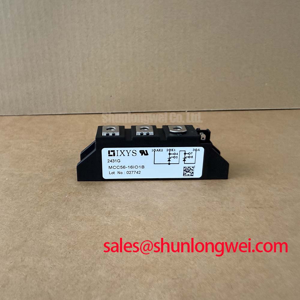
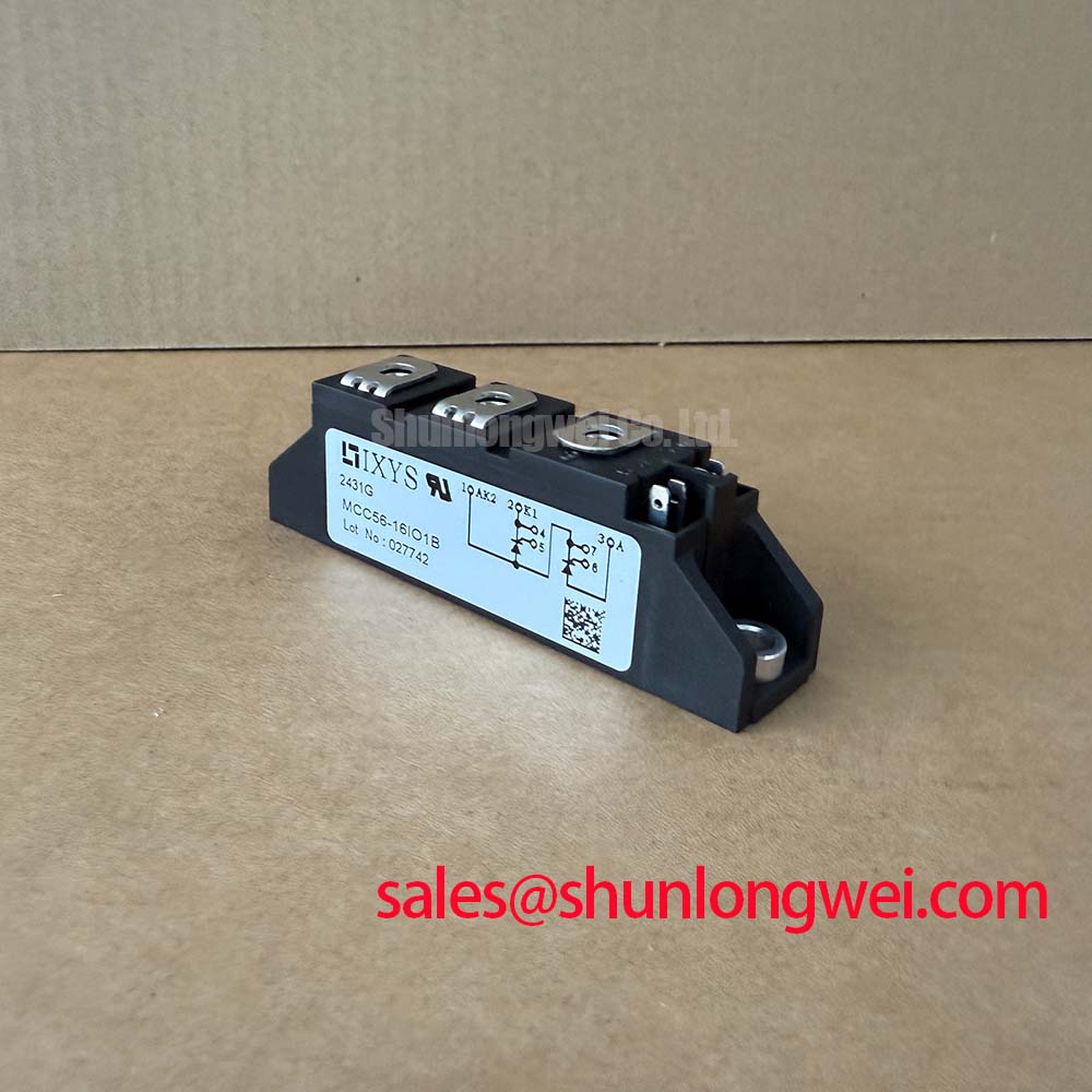
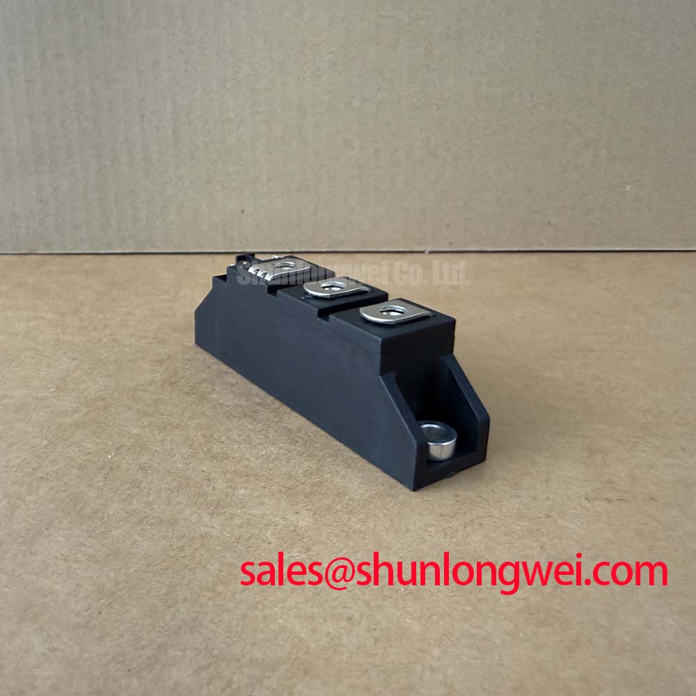
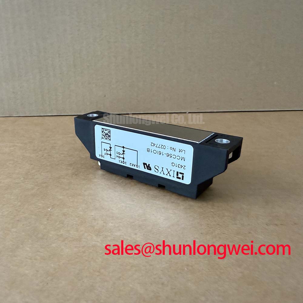
Before installation, verify the nameplate rating against the rectifier schematic, then confirm that the AC terminals, DC output terminals, gate leads, heatsink interface, and fuse position correspond to the original assembly. The IXYS MCC56-16IO1B is a dual thyristor module rated at 1600V VRRM/VDRM with an average on-state current of 60A at TC = 85°C. Its stated 920A, 10ms surge-current rating at 45°C, 4200 A²s I²t, 3600V~ isolation voltage, and 1000 V/µs critical dv/dt define the electrical boundaries that should be checked before it is evaluated for a phase-controlled power stage.
| Official Specification | MCC56-16IO1B Value | Integration Relevance |
|---|---|---|
| VRRM / VDRM | 1600V | Reverse and repetitive off-state blocking capability |
| ITAV | 60A at TC = 85°C | Average on-state current boundary |
| ITSM | 920A, 10ms, 45°C | Specified surge-current capability |
| I²t | 4200 A²s | Fuse-coordination reference |
| VISOL | 3600V~ | Isolation boundary between circuit and baseplate |
| Critical dv/dt | 1000 V/µs | Off-state transient-voltage tolerance reference |
Gate-drive verification should begin with an isolated oscilloscope measurement of the firing waveform at the actual module gate and cathode reference points, rather than at the controller output. A steep gate-current leading edge can support decisive triggering, while a sustained pulse-train strategy may be evaluated where source impedance, line distortion, or load behavior makes a single firing pulse less repeatable. The system integrator should verify gate-pulse timing against the original control board documentation and the applicable IXYS gate-trigger data.
The 60A average-current rating is an Official Datasheet Specification at a case temperature of 85°C; it is not a guarantee of current capability in a specific cabinet. Design Consideration: inspect the gate-return routing, terminal condition, and firing-transformer polarity, where a firing transformer is used, because an unstable gate reference or insufficient holding conditions can prevent normal current transfer after triggering.
Practical safety note: Isolate the power source and confirm that stored DC-link energy is discharged before disconnecting gate or power terminals.
Fuse selection should be checked through a time-current and I²t coordination review. The module’s stated 4200 A²s I²t value is an Official Datasheet Specification and provides a boundary for this review; the protective-device choice must still be verified against the prospective fault current, conductor arrangement, and upstream protection of the actual equipment.
Transient Dynamics & Electrical Design: Evaluating Post-Surge Reverse Voltage Blocking on MCC56-16IO1B
After a line-side disturbance or load fault, inspect the waveform sequence before allowing repeated restart attempts. The MCC56-16IO1B has an Official Datasheet Specification of 920A ITSM for a 10ms surge at 45°C. This is a defined surge condition, not a recurring operating-current rating. A post-event assessment should consider the measured half-cycle current, thermal state, fuse response, and the point at which reverse blocking voltage returns to the thyristor.
The 1600V specified repetitive off-state voltage rating establishes the module’s blocking boundary. Design Consideration: capture voltage at the power terminals with a suitable differential measurement arrangement and compare peak behavior with the DC or line-side conditions in the original circuit. This helps distinguish a supply transient, wiring-induced overshoot, firing anomaly, or load-side event without assigning a single cause from one symptom.
For a repair comparison, PD25016A can be reviewed as a separate dual-thyristor module listing. Terminal geometry, voltage class, current rating, isolation requirements, gate characteristics, heatsink interface, and protection coordination must all be confirmed by the system engineer before any interchange assessment.
Assembly Integrity & Layout Architecture: Implementing Surge Energy Dissipation and Clamping Voltage for MCC56-16IO1B
Inspect the mounting plane for flatness, contamination, uneven compound coverage, and evidence of unequal clamping force before energizing the assembly. The module mounting torque is system and hardware dependent unless specified in the applicable package documentation; it should therefore be verified from the original IXYS mechanical information and equipment service data. Terminal connections also require a clean, correctly aligned contact surface and torque verified for the installed terminal hardware.
Design Consideration: keep the high-current commutation path compact and arrange paired conductors with close, symmetrical geometry where practical. This reduces parasitic loop inductance that can contribute to turn-off overshoot. Where MOVs or RC snubbers are present ahead of the thyristor junctions, their voltage class, energy capability, placement, and capacitor condition should be validated against the measured surge environment and the system protection design.
The official 1000 V/µs critical dv/dt rating is relevant when reviewing commutation transients and noise immunity. It should not be treated as a system-level EMC certification. A useful thermal-design reference is The Advanced Thermal Management Revolution, particularly when evaluating the complete heat path from semiconductor module to heatsink and enclosure airflow.
Benchtop Waveform Tuning: Managing Harmonic Current and Line Filtering on MCC56-16IO1B
For phase-controlled conversion, vary the firing angle across the intended operating range and record line current, load current, supply voltage, and gate timing on the same time base. Delayed firing changes the conduction interval and can increase reactive-power demand and harmonic content. The firing controller should therefore be assessed with the connected load, line impedance, and any input filtering used by the original equipment rather than through a no-load waveform alone.
In a medium-frequency induction melting or hardening furnace power supply, engineers may evaluate this 1600V, 60A module within an input rectifier or controlled supply section, subject to the complete topology and thermal design. Engineering Recommendation: use measured current and voltage waveforms to verify whether line filters, commutation networks, and the firing schedule maintain suitable margins during load changes. Long output conductors can also introduce reflected transient behavior, so measurements should be taken at both the source-side and load-side locations when the system layout makes that relevant.