




Content last revised on September 12, 2026
MCNA220PD2200YB Circuit Protection & Reliability: Calibrating ITSM Safety Derating across Repetitive Current Stress
| Manufacturer | IXYS |
| Product category | Thyristor/Diode Module |
| Package | Phase-leg Thyristor/Diode Module |
| Official voltage rating | 2200 V |
| Official current rating | 220 A |
| Topology | General Power Stage |
| Series | Standard |
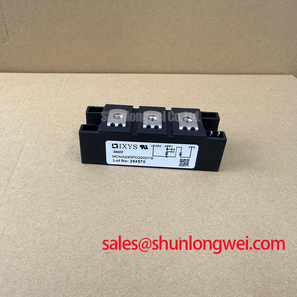
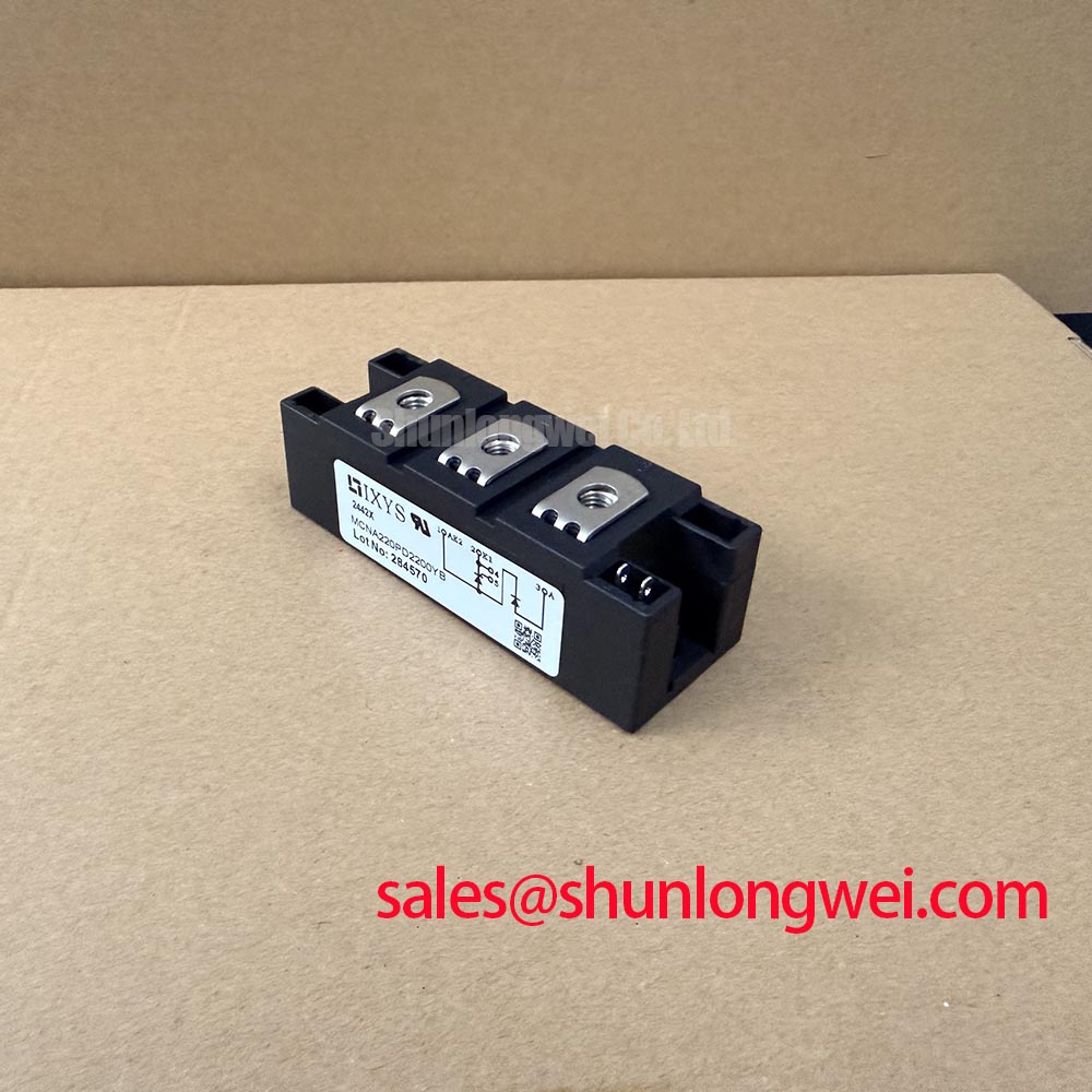
Isolate the assembly, discharge the connected capacitor bank by the equipment-approved method, and compare each accessible power-terminal conduction path with the original circuit drawing before reconnecting a MCNA220PD2200YB. This IXYS phase-leg thyristor/diode module carries official ratings of 2200 V and 220 A; these values establish the module’s published voltage and current identity, not a complete fault-energy or surge-duty allowance.
For repetitive current-stress assessment, record the actual line waveform, switching sequence, ambient condition, and heatsink condition from the equipment. The ITSM surge-current figure and associated conditions must come from the applicable manufacturer datasheet revision before it is used for protection coordination. A fuse I²t table should then be reviewed against the module’s documented non-repetitive surge capability, including the stated starting junction condition and half-cycle test basis. This is an Engineering Recommendation: preserve a traceable comparison between the fuse documentation, measured prospective fault current, and the module documentation rather than assigning a generic derating percentage.
In grid-tied static var compensator and thyristor-switched capacitor equipment, inspect busbar contact faces, terminal hardware, and phase-leg routing for heat discoloration, loose contact evidence, or unequal mechanical loading. A high-resistance terminal joint can alter the observed current distribution and make a protection event appear to originate inside the semiconductor stage. Use the original terminal designation drawing for all continuity and diode-mode measurements; do not infer terminal identity from package position alone.
💡 Bench Tip: Establish cold-state diode-mode readings with an ESD-controlled meter setup and compare them with a known-good circuit path before interpreting any individual reading as a device defect.
MCNA220PD2200YB Thermal-Electrical Optimization: I²t Sub-Cycle Melting Rating Practical Tuning
Capture the fuse clearing waveform at the protected branch and verify whether the interruption occurs before the semiconductor’s documented surge and I²t limits are exceeded. The MCNA220PD2200YB is officially specified as a 2200 V, 220 A IXYS thyristor/diode module, while fuse melting and clearing data belong to the selected protective device and the actual system fault loop.
Fuse coordination is a Design Consideration, not an inherent module feature. Review both pre-arcing I²t and total clearing I²t from the fuse manufacturer, then compare their stated test conditions with the module’s published withstand information. Cable length, transformer impedance, capacitor-bank energy, and the closing angle of a thyristor-switched capacitor branch can materially change the fault waveform. Oscilloscope records and protection-event logs provide a more useful basis for evaluation than a nominal current label alone.
Keep the mechanical path under the same level of scrutiny as the electrical path. Clean, flat mating faces and consistent tightening order help prevent uneven contact pressure between the module base and heatsink. Mounting torque must follow the package-specific IXYS mechanical documentation; it should not be substituted with a generic torque value. At the power terminals, use the specified hardware and tighten in the documented sequence so terminal stress is not transferred into the module body.
For a broader comparison of power-semiconductor implementation options, engineers can review the SEIKO product area while keeping voltage class, current class, package geometry, control topology, and original protection coordination as separate verification items.
MCNA220PD2200YB Thermal-Electrical Optimization: IEC 61000-4-5 Industrial Surge Immunity: Practical Tuning
Probe the voltage appearing at the protected AC branch during representative switching and surge-validation work, then compare the measured peak and ringing behavior against the 2200 V official module rating and the system’s approved protection limits. The module rating alone does not establish whole-equipment surge immunity or EMC compliance.
MOV and RC snubber selection is a system-level Design Consideration. Their placement, energy capability, repetitive duty, and coordination with the source impedance must be assessed around the actual capacitor-switching topology. The practical objective is to limit transient stress at the thyristor/diode terminals while confirming the resulting waveform with suitably rated measurement equipment. Verify peak margins against the DC-link or AC-bus conditions during switching tests rather than applying an unsupported universal component value.
The diode portion should be evaluated with reverse-recovery behavior and commutation conditions relevant to the original equipment, particularly where a switching capacitor stage creates abrupt current transfer. The IEC 60747-2 semiconductor diode standard is a useful external reference point for terminology and diode-device assessment. For related system-level component research, the TRIQUINT-SEMICONDUCTOR product area can be considered as a neutral reference source.
Do not describe this module as independently compliant with an equipment-level surge or EMC standard. Such compliance depends on the assembled cabinet, protective network, wiring layout, grounding arrangement, and formal test configuration.
Benchtop Waveform Tuning: Mitigating Stress via Mechanical Mounting Torque Sequence and Thermal Interface on MCNA220PD2200YB
Apply thermal compound as a controlled, continuous interface layer, mount the module using the documented cross-pattern sequence, and inspect the contact imprint after removal from a test fit if uneven pressure is suspected. Thermal resistance from junction to case, Rth(j-c), must be taken from the applicable IXYS datasheet before calculating temperature rise or assigning continuous-duty capability.
With the module operating in a controlled test arrangement, observe line current, terminal voltage, and heatsink temperature through the expected switching sequence. A waveform that changes after reassembly may indicate altered terminal inductance, interface pressure, conductor routing, or a change elsewhere in the protection network. It does not by itself prove an internal semiconductor failure. Maintain the original busbar stack-up and avoid forcing conductors into alignment after the mounting hardware has been tightened.
For reliability-focused design discussion around newer power-switching technologies, see Wide Bandgap Revolution. That resource supports technology comparison, while integration of this phase-leg thyristor/diode module remains governed by its documented ratings, package drawing, protection coordination, and validated equipment waveform.
Power-module context is also available from Shindengen Power Semiconductor Modules & Diodes. For equipment repair, retain the measured cold-state reference readings, thermal-interface observations, and switching captures with the service record so subsequent replacement verification uses the same electrical baseline.