Content last revised on September 25, 2026
Transient Dynamics and Electrical Design: AC Input Overvoltage Protection for MDC100-14
The 1400 V VRRM rating defines the repetitive reverse-voltage boundary published for the MDC100-14. During evaluation of an AC input rectifier, engineers should compare the measured line condition, transformer leakage behavior, commutation overshoot, and surge-protection response with this official specification. The rating should not be treated as permission to expose the module directly to uncontrolled transient energy.
A metal oxide varistor network may be evaluated ahead of the rectifier to limit incoming surge voltage, while an RC snubber can be considered where switching or commutation produces excessive local voltage ringing. MOV selection is system-dependent. The integrator should verify its continuous operating voltage, surge class, energy capability, aging behavior, and coordination with the upstream protection device against the actual AC supply and transformer configuration.
IEC 61000-4-5 testing may be relevant to the complete power-conversion assembly, but the MDC100-14 itself should not be described as independently compliant with an equipment-level EMC or surge standard. The complete rectifier requires controlled testing at its defined ports. Minimize the high-current commutation loop and verify peak reverse voltage at the module terminals with suitable probing practice.
Before energizing a replacement module, identify every terminal from the original assembly drawing or manufacturer documentation. Do not infer anode, cathode, or common-terminal arrangement from physical position alone. A cold diode-test comparison can help identify an abnormal junction, but it is not a substitute for a controlled high-voltage insulation test performed with the module disconnected from sensitive circuitry.
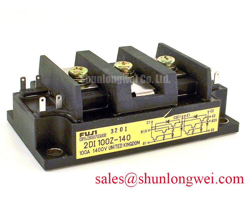
The related 2DI100Z-140 can be reviewed as a same-category reference during topology and rating comparisons. Any substitution decision still requires confirmation of terminal arrangement, mechanical fit, thermal path, and electrical specifications.
MDC100-14 Circuit Protection and Reliability: Reviewing IFSM Under Repetitive Surge Conditions
The official IFSM rating is 2250 A at 60 Hz. This value describes surge-forward-current capability under the manufacturer’s stated test conditions; it is not a continuous operating current and should not be used as a routine overload target. For a rectifier feeding an electrolyzer DC bus, the engineer should examine transformer energization, capacitor charging, fault clearing, and repeated restart behavior separately.
When the power stage experiences a sinusoidal fault or startup surge, record the current waveform, pulse duration, repetition pattern, and junction-temperature condition. A single surge event and repeated surge exposure can produce different thermal stresses. The 100 A IF(AV) rating at Tc = 98°C also requires attention to the case-temperature reference. Actual allowable current depends on the heatsink, interface condition, airflow or coolant arrangement, electrical waveform, and the thermal resistance of the assembled system.
Semiconductor fuse selection should be coordinated with the fuse manufacturer’s published clearing-energy and I²t data. The MDC100-14 parameter set supplied here does not include a fuse I²t coordination table, so a specific fuse model or fault-clearing time should not be presented as a factory-approved match. Designers should compare the prospective fault current and clearing behavior with the complete rectifier protection study.
After a surge event, allow the assembly to reach a safe, controlled condition before applying reverse voltage again. Inspect for discoloration, loosened terminals, cracked insulation, or a changed diode-test result. A changed reading may indicate electrical stress, but diagnosis should be confirmed by comparing the affected path with a known-good module and by performing the applicable insulation and high-voltage tests under an approved service procedure.
For broader power-device context, the Unlocking Efficiency in Industrial Drives reference discusses switching-device efficiency considerations. It should not be interpreted as a datasheet extension for this IXYS diode module.
Assembly Integrity and Layout Architecture: Short-Circuit Protection Limits
The 1.30 V maximum forward voltage drop is an official electrical parameter that affects conduction-loss estimation at the specified test condition. It should not be converted directly into a complete heatsink requirement without the actual current waveform and thermal model. In a high-current DC rectifier, both conductive loss and transient fault energy must be considered during assembly validation.
For short-circuit protection, the semiconductor fuse must clear the fault before the diode module is exposed to energy beyond its permitted operating conditions. Compare the fuse manufacturer’s total clearing I²t with the semiconductor manufacturer’s published withstand information for the exact fault path. Because a complete coordination table is not included in the supplied MDC100-14 data, the final protection choice should be validated through documented system calculations and controlled testing rather than by assuming that a nominal fuse current is sufficient.
Mechanical installation is equally important. The module mounting surface should be clean, flat, and free from burrs or foreign material. Use the original assembly documentation to confirm the specified clamp method, washer arrangement, terminal hardware, and tightening torque. Excessive or uneven pressure can compromise the package or thermal interface, while insufficient pressure can increase thermal resistance and produce local heating.
💡 Bench Tip: Keep the module protected from electrostatic discharge and compare cold-state diode readings with a documented known-good reference before applying high voltage.
The 2500 V isolation breakdown voltage is the published isolation rating for the module. It should be evaluated together with the heatsink, mounting hardware, interface material, contamination level, creepage, clearance, and the test method used by the finished equipment. It does not independently certify the insulation system of a hydrogen-electrolyzer rectifier cabinet.
For moisture and reflow-related semiconductor handling references, consult JEDEC J-STD-020. That document addresses moisture sensitivity and reflow classification; it should not be assumed to define the field installation or high-voltage qualification of this power module. Likewise, the material discussion at Silicon Carbide Semiconductor Physics concerns SiC technology and should not be used to infer an SiC construction for the MDC100-14.
Preventing Spurious Faults: Isolated Firing and Rectifier Control Review
The supplied factory data identifies the MDC100-14 as a dual diode module and provides voltage, current, surge, forward-drop, and isolation ratings. It does not provide gate-drive requirements, pulse-transformer specifications, gate threshold data, holding-current data, or firing-pulse rise-time limits. A firing circuit should therefore not be assigned thyristor-style gate parameters without first confirming the actual circuit topology and the manufacturer’s complete datasheet.
If the module is being installed in a rectifier assembly that also contains controlled semiconductor stages, keep the isolated firing circuit electrically separate from the high-current diode path and verify signal polarity at the intended controlled devices. Pulse-transformer insulation, reset behavior, common-mode transients, and control-reference placement should be checked under the real switching waveform. An oscilloscope comparison with the original working channel can help identify timing or coupling anomalies without assuming a single fault cause.
The 2500 V isolation breakdown voltage supports an insulation review for the module, but the transformer, PCB, wiring harness, heatsink, and enclosure must each satisfy the system’s insulation requirements. Designers should verify creepage and clearance against the applicable equipment standard and operating environment. No independent EMC, safety, or functional certification should be inferred from the module rating alone.
In a high-current green hydrogen electrolyzer DC power rectifier, the adjacent transformer, upstream protection, DC-link capacitance, cooling path, and control cabinet determine the final stress applied to the diode module. The neutral reference MSKD36-18 may be reviewed as a related rectifier-stage component, but compatibility must be established from the original circuit documentation, terminal map, thermal design, and measured operating waveform.