

Content last revised on September 20, 2026
MDC100-6 Circuit Protection and Reliability in 6-Pulse and 12-Pulse Rectifiers
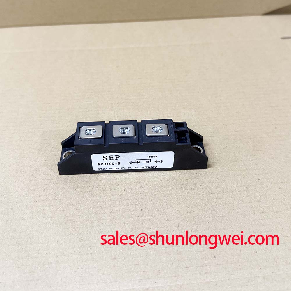
Check the module marking, inspect the case and terminals, and verify the original rectifier’s electrical limits before energizing a replacement IXYS MDC100-6. The supplied factory data identifies a dual diode module with a 600 V repetitive peak reverse voltage, a 600 V repetitive peak off-state voltage, and an average forward current of 110 A at TC = 85 °C. These values should be checked against the equipment documentation rather than treated as a complete system rating.
| Parameter | Official Specification | Condition |
|---|---|---|
| Repetitive Peak Reverse Voltage, VRRM | 600 V | Factory specification |
| Average Forward Current, ID(AV) | 110 A | TC = 85 °C |
| Repetitive Peak Off-State Voltage, VDRM | 600 V | Factory specification |
| Isolation Test Voltage, VISOL | 2500 V AC RMS | 50/60 Hz, 1 minute |
| Operating Junction Temperature, Tvj | −40 to +125 °C | Factory specification |
| Thermal Resistance, RthJC | 0.35 K/W per diode | Junction to case |
| Typical Weight | 150 g | Factory specification |
For a high-current green hydrogen electrolyzer DC power rectifier, the first integration task is to confirm the circuit position occupied by the original module. A six-pulse bridge normally uses three phase branches, while a twelve-pulse arrangement uses two six-pulse bridges with phase displacement and an interphase transformer or equivalent current-sharing network. The MDC100-6 should be evaluated against the actual bridge topology, the transformer arrangement, the DC-link operating voltage, and the required continuous current.
The 110 A ID(AV) rating at TC = 85 °C is an official device specification, not a guaranteed converter output rating. Enclosure temperature, heatsink performance, current waveform, duty cycle, airflow, and parallel branch balance all affect the usable system current. The module’s rating must also be reconciled with the circuit’s conduction path and the equipment manufacturer’s application documentation.
Fuse coordination requires the original fuse class, clearing characteristic, prospective fault current, and the module’s applicable surge-current or I²t data from the correct IXYS documentation. Those fuse coordination values are not included in the supplied parameter set, so designers should not infer them from the average current rating. During service evaluation, record the fuse part number, terminal arrangement, conductor routing, and measured voltage across each bridge branch.
For a twelve-pulse system, inspect the interphase transformer connections and current-sharing behavior before replacing only one branch. Unequal branch current can produce a thermal pattern that appears to be a module problem while originating in transformer phasing, connection resistance, or control synchronization. The neutral reference for any measurement should follow the equipment schematic, and high-voltage testing should be performed with suitable isolation and lockout procedures.
Preventing Spurious Faults in Triggered Rectifier Assemblies
The supplied product data describes diode ratings and does not provide gate trigger current, gate trigger voltage, gate pulse rise time, holding current, or latching current values. Those parameters must not be assigned to the MDC100-6 without confirming the exact manufacturer datasheet and internal device construction. A diode bridge replacement should not be driven with a thyristor gate-control strategy simply because a related rectifier assembly uses controlled devices elsewhere in the power stage.
Where the surrounding converter includes triggered semiconductor devices, the maintenance engineer should trace the firing circuit independently from the MDC100-6 replacement decision. Check pulse timing, transformer isolation, return paths, connector condition, and synchronization between parallel or phase-shifted bridges. If a waveform appears abnormal, compare it with a known-good phase using a properly rated differential probe and observe the device terminal voltage during commutation.
Gate-loop parasitic inductance and ringing are system-level concerns for any nearby controlled semiconductor. The design consideration is to keep high-current commutation paths compact and to control ringing through an experimentally verified damping network, while the final values remain determined by the converter layout, switching edge, insulation system, and measured peak voltage. No gate-drive number should be transferred to this module from another IXYS part without documentation.
For a suspected intermittent rectifier fault, inspect the terminal clamping surfaces, cable lugs, busbar alignment, and control harness separately. A loose power connection, a damaged trigger transformer, or incorrect phase sequence can produce symptoms that resemble semiconductor failure. Capture the fault condition before removing the module whenever the equipment safety procedure permits it.
Assembly Integrity and Uniform Heatsink Contact
The thermal data makes the mounting interface a primary inspection point. The stated RthJC is 0.35 K/W per diode under the supplied factory definition. This is a junction-to-case value; it does not include the interface material, heatsink, mounting hardware, airflow, or cabinet temperature. The equipment thermal design must therefore be verified from the complete thermal path rather than from the module rating alone.
Before installation, clean the heatsink contact area according to the equipment maintenance procedure and check for burrs, distortion, embedded debris, or corrosion. The module base should sit evenly against the heatsink without rocking. Thermal interface material should be applied as a thin, continuous layer appropriate to the selected compound and surface finish; excessive compound can increase interface resistance and contaminate nearby insulation.
The supplied factory information does not specify a mounting torque, fastener size, baseplate flatness tolerance, or terminal tightening torque. These values should be taken from the applicable IXYS mechanical drawing or the original equipment service manual. Do not substitute a generic torque value where the module drawing specifies a different hardware arrangement. Tighten progressively and evenly so that the baseplate is not distorted during clamping.
After reassembly, inspect the heatsink fan, air path, dust filters, and cabinet ventilation. A temperature comparison between corresponding bridge positions can help identify uneven contact or branch imbalance, but the readings should be interpreted alongside load current, ambient temperature, and airflow. ⚠️ Maintenance Note: de-energize and discharge the converter before touching terminals, and include periodic heatsink cleaning and contact-temperature checks in the preventive maintenance schedule.
For installations exposed to low temperatures, humidity, or condensation, verify enclosure heating, drainage, and insulation condition. The official operating junction range is −40 to +125 °C, but this does not by itself certify cabinet operation under condensation, salt contamination, or repeated thermal cycling. Those environmental controls remain system responsibilities.
Benchtop Waveform Tuning and Surge-Current Verification
A ten-millisecond half-cycle surge test should be treated as a controlled engineering evaluation, not as proof of continuous operating capability. The supplied data does not include an ITSM surge-current value, its test waveform, or the permitted recovery interval before reverse voltage is reapplied. Consequently, the MDC100-6 must not be assigned a surge limit from the 110 A average forward-current rating.
When analyzing a rectifier waveform, record the applied AC voltage, conduction interval, peak current, junction or case temperature, and the time between the current pulse and the next reverse-voltage condition. The test fixture should reproduce the intended source impedance and wiring inductance closely enough to make the result useful. A bench result obtained with short leads and a low-energy source may not represent the electrolyzer rectifier cabinet.
Before reapplying reverse voltage after a high-current pulse, verify that the device temperature and the surrounding assembly have returned to an approved operating condition defined by the system design. The 600 V VRRM and 600 V VDRM ratings are official voltage limits under their specified conditions; they do not establish a universal transient margin for an inductive bridge. Peak voltage should be measured at the module terminals, including the effect of busbar and commutation-loop inductance.
In a twelve-pulse converter, compare the two bridge waveforms for phase alignment and current sharing. In a six-pulse converter, inspect each phase branch for consistent conduction timing and terminal voltage. If one branch shows abnormal overshoot, delayed recovery, or a different thermal response, check transformer connections, fuses, cabling, and measurement references before assigning the cause to the semiconductor.
For broader selection work involving voltage, current, thermal interface, and application constraints, engineers can consult the Power Semiconductor Selection Guide. A neutral comparison point for a related high-current module is RM100HA-20F; any substitution requires confirmation of topology, ratings, mechanical fit, isolation, and the original equipment documentation.
Deep-level transient spectroscopy is a characterization method associated with defect and trapping analysis in semiconductor materials, but it is not a field acceptance test for this rectifier module. Background reading is available through Deep-Level Transient Spectroscopy. Field troubleshooting should remain based on controlled electrical measurement, thermal inspection, and comparison with the approved circuit documentation.