


Content last revised on February 1, 2026
MG100J2YS1 Datasheet & Technical Review: A 600V, 100A Dual IGBT Module for Industrial Power Systems
Introduction: A Focused Look at the MG100J2YS1
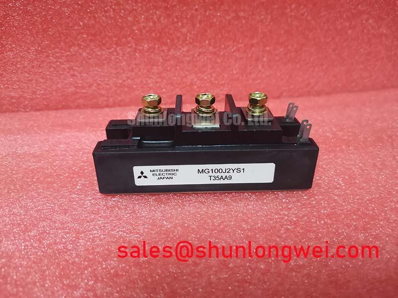
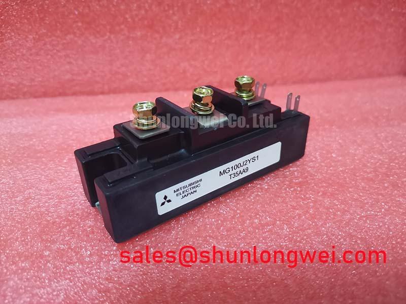
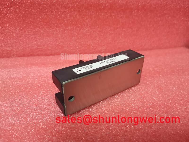
Engineered for reliability in medium-power industrial systems, the Toshiba MG100J2YS1 is a robust 600V/100A half-bridge IGBT module. It offers a well-defined platform for power conversion, combining key specifications like a 600V collector-emitter voltage, 100A DC collector current, and a maximum VCE(sat) of 2.7V. This component provides proven performance for established designs and offers a straightforward path for implementing a single-phase or one leg of a three-phase inverter. Its thermal characteristics are pivotal for determining appropriate heatsinking, which directly influences the final system's physical footprint and long-term operational stability under demanding load cycles.
Key Parameter Overview
Decoding the Specs for Thermal Management and Power Handling
The technical specifications of the MG100J2YS1 provide the necessary data for robust system design, particularly concerning thermal and electrical load management. The values below are extracted from the official datasheet and represent the component's absolute maximum ratings and key electrical characteristics under specified test conditions.
| Parameter | Symbol | Condition | Value |
|---|---|---|---|
| Collector-Emitter Voltage | Vces | Vge = 0V | 600V |
| Gate-Emitter Voltage | Vges | ±20V | |
| Collector Current (DC) | Ic | Tc = 25°C | 100A |
| Collector Current (1ms Pulse) | Icp | Tc = 25°C | 200A |
| Collector Power Dissipation | Pc | Tc = 25°C (Per IGBT) | 390W |
| Junction Temperature | Tj | 150°C | |
| Collector-Emitter Saturation Voltage | VCE(sat) | Ic = 100A, Vge = 15V | 2.7V (Max) |
| Gate-Emitter Leakage Current | Iges | Vge = ±20V | ±500nA |
| Thermal Resistance (Junction to Case) | Rth(j-c) | Per IGBT | 0.4 °C/W |
Download the MG100J2YS1 datasheet for detailed specifications and performance curves.
Application Scenarios & Value
System-Level Benefits in Motor Drives and Power Conversion
For cost-sensitive 240V AC motor drives up to 15kW where robust thermal design is prioritized, the MG100J2YS1 offers a proven solution. Its primary value is demonstrated in applications where predictable performance and durability are paramount.
- Variable Frequency Drives (VFDs): In VFDs controlling AC induction motors, the MG100J2YS1's 100A current rating comfortably manages the power requirements for many medium-duty industrial loads. The critical challenge in these systems is managing heat, especially during low-speed, high-torque operation where conduction losses are significant. The module's specified thermal resistance provides the exact data needed for effective heatsink design, ensuring system reliability.
- Switch Mode Power Supplies (SMPS): For industrial-grade SMPS and UPS (Uninterruptible Power Supply) systems, the half-bridge topology simplifies the power stage layout. The 600V Vces offers a sufficient safety margin for applications running on 200/240V AC lines.
- Welding Power Supplies: The module's pulsed current capability (200A) makes it a viable candidate for the inverter stage of welding equipment, which demands robust components capable of handling intermittent high-energy cycles.
While the MG100J2YS1 is well-suited for these applications, for systems requiring operation on 480V AC lines, the related MG150Q2YS50 provides a higher blocking voltage of 1200V.
Frequently Asked Questions (FAQ)
Engineering Inquiries on Performance and Implementation
How does the VCE(sat) of 2.7V impact the thermal design for the MG100J2YS1?
The 2.7V VCE(sat) is a direct multiplier for conduction losses (Power Loss = VCE(sat) × Collector Current). At its rated current of 100A, this results in 270W of heat generated from conduction alone per switch. A design engineer must use this value as a primary input for thermal calculations to ensure the junction temperature does not exceed the 150°C maximum, which requires an appropriately sized heatsink.
What is the significance of the dual IGBT (half-bridge) configuration in this module?
The dual, or half-bridge, configuration integrates two series-connected IGBTs into a single package. This simplifies the design and assembly of common power topologies. It can directly implement a single-phase inverter leg or, by using three modules, a complete three-phase inverter, reducing component count and simplifying the PCB layout compared to using discrete IGBTs.
Given its specifications, is the MG100J2YS1 suitable for high-frequency switching applications?
The datasheet does not detail switching losses (Eon, Eoff), which is typical for older-generation IGBTs. However, the relatively high VCE(sat) suggests it is optimized for lower to medium switching frequencies (typically below 20 kHz). At higher frequencies, switching losses would likely become the dominant source of heat, potentially exceeding the module's thermal dissipation capabilities. A robust gate drive design is essential to minimize these losses.
Technical Deep Dive
Analyzing Conduction Losses and Thermal Resistance for Reliable Operation
Understanding the thermal behavior of the MG100J2YS1 is not just an academic exercise; it's fundamental to its successful deployment. The two parameters at the heart of this analysis are the Collector-Emitter Saturation Voltage (VCE(sat)) and the Thermal Resistance, Junction-to-Case (Rth(j-c)).
Think of VCE(sat) as the "operational cost" or "toll" that current pays to flow through the IGBT when it is fully on. For the MG100J2YS1, this toll is a maximum of 2.7 volts at 100 amps. This means in a DC state, the device generates 270 watts of heat (2.7V × 100A). This conduction loss is the primary source of heat in low-frequency applications like motor control at low speeds and must be effectively managed. What dictates thermal design when using this module? Its VCE(sat) of 2.7V and Rth(j-c) of 0.4 °C/W are the critical factors.
If VCE(sat) is the source of heat, Rth(j-c) governs how efficiently that heat can be evacuated. This parameter can be imagined as the "width of a thermal highway" from the hot silicon die to the module's copper baseplate. A lower Rth(j-c) signifies a wider, more efficient highway. The MG100J2YS1's value of 0.4 °C/W means that for every watt of power dissipated, the junction temperature will rise 0.4°C above the case temperature. An engineer armed with this specific value can accurately predict the junction temperature and select a heatsink that prevents the device from entering a thermal runaway condition.
Application Vignette
Case Study: Designing a Robust 10kW VFD with the MG100J2YS1
An engineering team is tasked with developing a compact and reliable 10kW Variable Frequency Drive (VFD) for a conveyor system in a manufacturing plant. The system is subject to frequent start-stop cycles and must handle brief overload currents during motor startup. The primary design challenge is to create a power stage that is both cost-effective and thermally stable, avoiding nuisance trips from overheating without using an excessively large and expensive heatsink.
The team selects the MG100J2YS1 for one of the inverter legs. By referencing the datasheet, they confirm that the Safe Operating Area (SOA) curves accommodate the expected overload profiles. The core of their design process becomes a thermal analysis based on the module's key specifications. They calculate the total power dissipation as the sum of conduction and switching losses (P_total = P_conduction + P_switching). With a VCE(sat) of 2.7V and an estimated switching frequency, they establish a worst-case power dissipation budget. Using the Rth(j-c) of 0.4 °C/W, they model the temperature rise from the case to the junction. This allows them to specify the maximum allowable thermal resistance for the heatsink (Rth(c-a)) to ensure the junction temperature (Tj) remains safely below the 150°C limit, even under worst-case ambient temperature and load conditions. This data-driven approach, centered on the module's defined thermal characteristics, allows for a precisely engineered solution that balances reliability, cost, and physical size.
Strategic Positioning
The MG100J2YS1 holds a strategic position for engineers focused on the maintenance, repair, and operation (MRO) of existing industrial equipment. Its proven design provides a reliable solution for extending the life of systems where qualifying a newer-generation component would be cost-prohibitive or time-consuming. For new, cost-sensitive projects in the medium-power range, this module offers a known quantity, allowing designers to leverage established design principles and ensure predictable system behavior without the complexities associated with cutting-edge semiconductor technologies. It represents a balance of capability and practicality for a specific class of industrial power applications.