
Content last revised on September 10, 2026
Turn-Off di/dt Induced V_peak Clamping and Snubber Capacitor Sizing
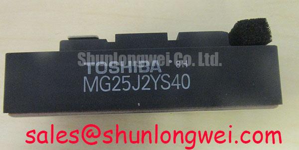
In high-speed robotic servo drives and automated pick-and-place actuators, switching transients demand strict management of parasitic bus inductance. The MG25J2YS40 is configured as a dual-IGBT half-bridge module rated for a maximum Collector-Emitter Voltage of VCES = 600V (Official Datasheet Specification) and a continuous Collector Current of IC = 25A at DC (Official Datasheet Specification), with short-duration repetitive peaks reaching ICP = 50A (Official Datasheet Specification). When turning off inductive loads, rapid collector current decay generates an induced overvoltage spike across the parasitic loop inductance that adds directly to the nominal DC bus potential.
Because the factory turn-off fall time reaches a maximum of tf = 0.35µs (Official Datasheet Specification), steep current transitions occur during hard turn-off events. Under switching conditions where the rate of current decay reaches 200 A/µs, an unmitigated parasitic loop inductance of 50 nH can introduce an overvoltage transient of 100V. Superimposing this overvoltage onto a 380V rectified DC rail reduces the voltage safety margin relative to the 600V absolute rating. Maintaining a low bus inductance below 25 nH (General Industry Design Consideration for compact half-bridge modules) is critical to prevent dielectric overstress across the silicon die.
Minimizing this transient requires planar busbar structures where the positive and negative copper laminates overlap closely, maximizing mutual magnetic cancellation. In addition, low-inductance polypropylene film snubber capacitors (with typical capacitance values between 0.1 µF and 0.47 µF selected as a Typical Starting Point for bench tuning) must be connected directly across the main collector (C1) and power emitter (E2) screw terminals. This placement dampens high-frequency ringing, clamps turn-off spikes, and protects the freewheeling diode, which features an official reverse recovery time of trr = 0.15µs (Official Datasheet Specification).
Multi-Module Parallel Current Sharing & Positive Tempco Dynamic Balancing
Multi-joint articulated robotic arms frequently operate under cyclical acceleration and dynamic load reversals. When drive topologies require higher output current than a single 25A channel provides, modules are occasionally paralleled across common motor phases. Effective static current sharing in parallel configurations relies on the conduction characteristics of the IGBT die. At operating temperatures approaching the maximum rated junction temperature of Tj = 150°C (Official Datasheet Specification), the saturation voltage VCE(sat) exhibits a positive temperature coefficient at nominal current, naturally discouraging thermal runaway by shunting excess current toward cooler parallel branches.
Dynamic current balancing during switching intervals requires tight matching of gate drive timing and symmetry in power stage layout. Asymmetric gate trace lengths or uneven loop geometries cause transient current mismatches during the 0.35µs turn-off transition, concentrating thermal dissipation on the faster-switching silicon channel. For high-side gate drivers utilizing bootstrap supplies, the bootstrap capacitor must be sized to supply both the total gate charge and the driver quiescent current without dropping below the gate driver undervoltage lockout threshold. A minimum bootstrap capacitance calculation should provide at least ten times the equivalent gate charge capacity to maintain gate drive stiffness across variable PWM duty cycles.
Thermal stability across the drive assembly requires active temperature tracking. Design engineers integrate sensor feedback using external sensors or a Negative Temperature Coefficient (NTC) Thermistor in IGBT Modules positioned on the heatsink directly beneath the module baseplate. For legacy equipment overhauls or system upgrades requiring higher continuous current margins without altering the base drive layout architecture, the related MG50G2DM1 provides a 50A rating within a dual-pack footprint.
PCB Gate Loop Layout Symmetry & Kelvin Emitter Routing Optimization
Internal mutual inductance between the main power emitter and the gate control circuit is a primary source of high-frequency gate oscillations and spurious turn-on in fast-switching bridge topologies. The Toshiba MG25J2YS40 utilizes dedicated auxiliary emitter terminals to isolate the gate drive reference from the high-current output path. Injecting phase current fluctuations through a shared emitter path introduces an induced voltage that opposes driver gate signals, decelerating switching transitions and causing erratic threshold behavior.
💡 Bench Tip: During incoming quality inspection and static testing, always ground your ESD wrist strap before handling the control terminals. Verify the gate-emitter dielectric integrity using a specialized semiconductor curve tracer or high-impedance static meter, ensuring that applied gate potentials remain strictly within the official rated Gate-Emitter Voltage limit of VGES = ±20V (Official Datasheet Specification). Measure the forward voltage drop of the integrated anti-parallel diodes using a constant 10mA source to confirm junction integrity before mounting modules to the heatsink.
To eliminate unwanted parasitic feedback, PCB layouts must route the gate drive signal and auxiliary Kelvin emitter return as a tightly coupled differential pair directly to the driver output stage. This minimizes the physical gate loop area and shields the sensitive gate oxide from high di/dt fields generated by the motor cables. Comprehensive diagnostic procedures and static verification standards for industrial modules are detailed in our Field Engineer’s Handbook for component verification and failure analysis.
High-Altitude Cosmic Ray Induced SEB Failure & FIT Rate Mitigation
Industrial automation equipment installed at high altitudes (above 2000 meters) experiences increased exposure to terrestrial cosmic neutron flux. High-energy atmospheric neutrons colliding with the high-field depletion region of a reverse-biased IGBT can trigger localized avalanche multiplication, leading to Single Event Burnout (SEB). Because SEB occurs instantaneously without prior thermal degradation, mitigating this risk is essential for industrial robotic systems operating in high-elevation manufacturing facilities.
The cosmic-ray failure rate, expressed in Failures in Time (FIT, where 1 FIT equals 1 failure per 109 component operating hours), exhibits exponential dependence on the applied electric field across the collector-emitter junction. While the MG25J2YS40 carries a rated breakdown specification of VCES = 600V (Official Datasheet Specification) and a total power dissipation capability of PC = 100W (Official Datasheet Specification), continuous DC-link voltage selection dictates long-term reliability under cosmic radiation. Operating the DC bus at 300V to 380V provides a voltage headroom margin that maintains terrestrial neutron FIT rates well within standard light industrial reliability limits.
⚠️ Field Alert: When mounting the module to a liquid-cooled plate or extruded aluminum heatsink, verify baseplate flatness tolerances within 50 µm and apply a uniform thermal grease layer of 60–100 µm thickness. Torque the mounting screws progressively in a diagonal sequence to standard specifications (Design Consideration for M5 hardware), ensuring that the internal ceramic substrate is not subjected to mechanical bending stresses that could compromise the factory Isolation Voltage rating of Visol = 2500V AC for 1 minute (Official Datasheet Specification).