Content last revised on May 4, 2026
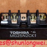
MG25N2CK1 Toshiba Power Module: Engineering-Grade Analysis of the 1100V Darlington Half-Bridge
Streamlining power stage design in high-voltage motor control through an integrated 1100V, 25A NPN Darlington half-bridge architecture. 1100V | 25A | Half-Bridge Configuration. Minimizes stray inductance. Simplifies heatsink mounting. What is the primary benefit of the MG25N2CK1 half-bridge design? It reduces parasitic inductance and simplifies PCB layout for inverters. For legacy 400V motor drives requiring high voltage margin, this 1100V Darlington module is the optimal choice.
Application Scenarios & Value
Addressing High-Voltage Switching Challenges in Industrial Automation
Engineers often face significant challenges when managing voltage transients in high-inertia motor control systems. The Toshiba MG25N2CK1 directly addresses this through its robust 1100V Vce rating. In applications like a heavy-duty Variable Frequency Drive (VFD) or an industrial UPS, inductive kickback during rapid deceleration can destroy power silicon.
The elevated 1100V margin provides a critical buffer over typical 400V or 480V bus voltages. This ensures the 25A Darlington module maintains its Safe Operating Area during extreme transient events. Additionally, this component is frequently deployed in legacy servo drive architectures where ruggedness is prioritized over maximum switching frequency.
For systems requiring higher current handling, the related MG150Q2YS50 offers a scaled-up capacity of 150A. Meanwhile, the MG400Q2YS60A pushes the boundary to 400A for grid-level infrastructure. Selecting the right module relies heavily on balancing voltage, current, and thermal management parameters across the entire system.
Technical Deep Dive
Decoding the NPN Triple Diffused Darlington Integration
The MG25N2CK1 operates as a "GTR MODULE SILICON NPN TRIPLE DIFFUSED TYPE." It functions fundamentally as a high-power Darlington pair arranged in a half-bridge layout. The Darlington configuration cascades two bipolar transistors. This enables an exceptionally high current gain from a relatively modest base drive signal.
Think of this NPN Darlington pair as a two-stage mechanical gear system. The first "gear" takes a low-power input effort and multiplies it to drive a massive secondary "gear." This effectively controls the full 25A load with minimal control-circuit overhead, streamlining the overall drive architecture.
Furthermore, the physical packaging employs an electrically isolated baseplate. The isolated baseplate functions like a specialized thermal highway. It conducts heat away from the silicon while acting as a concrete barrier against electrical faults. This eliminates the need for external insulating mica or ceramic pads. Consequently, thermal impedance is stabilized, and manufacturing cycle times are substantially compressed.
Key Parameter Overview
Functional Grouping of Critical Specifications
| Voltage Rating Group | Collector-Emitter Voltage (Vceo): 1100V |
| Current Rating Group | Continuous Collector Current (Ic): 25A |
| Structural Group | Configuration: Half-Bridge | Type: NPN Darlington |
| Isolation Group | Isolation Voltage (Viso): 2500V AC |
Download the MG25N2CK1 datasheet for detailed specifications and performance curves.
Frequently Asked Questions
Engineering Queries on Darlington Half-Bridge Modules
How does the 1100V rating of the MG25N2CK1 protect against motor drive transients?
The high 1100V collector-emitter threshold offers a vast safety margin above standard 400V industrial buses. This prevents avalanche breakdown during the inductive voltage spikes naturally generated when motor loads are abruptly disconnected or dynamically braked.
Why choose a Darlington GTR module over modern discrete topologies for legacy replacements?
For existing industrial chassis, matching original drive characteristics is paramount. The MG25N2CK1 provides the exact base-drive current requirements and thermal footprint of legacy systems. This prevents complete gate-drive redesigns mandatory when transitioning to discrete wide-bandgap devices.
Ensure your motor control infrastructure maintains operational continuity with verified components. Review your system's specific base-drive and thermal requirements against the official parameters to validate exact compatibility and maximize field reliability.