

Content last revised on October 16, 2026
MG25Q6ES43 Circuit Protection & Reliability: Calibrating Floating Gate Bias Supply Decoupling
Check the floating driver supply at its local reference while the high voltage DC link remains isolated. As a Design Consideration, the driver should establish its intended operating supply and a controlled gate state before the power stage receives bus voltage. Review the actual enable circuit, undervoltage lockout behavior, and shutdown path together: a supply indicator alone does not establish that the gate output remains controlled during startup or loss of auxiliary power.
Where the equipment uses negative gate bias, inspect that rail through startup, normal switching, and shutdown against the approved driver design. Negative bias is a system design choice, and its magnitude must remain within the device’s gate limits. An interlock should respond to an unsuitable driver supply by inhibiting switching through the equipment’s defined protection sequence. Verify the sequence with recorded waveforms, including the interval after the controller removes its enable signal.
Inspect local decoupling placement and the current path between the driver output stage, its supply capacitors, and its reference connection. As an Engineering Recommendation, keep this loop compact to reduce supply disturbances during gate charging and discharging. Assess capacitor condition, solder joints, connector resistance, and rail recovery under switching activity. Select capacitance and component ratings from the driver’s transient demand, supply impedance, temperature conditions, and validated control behavior.
Floating supply measurements require suitable isolated or differential instrumentation with ratings appropriate to the circuit. Observe the supply directly across its local terminals so that switching movement of the reference node does not obscure the result. If a gate disturbance coincides with an auxiliary rail dip, compare the timing against the protection output before assigning the fault to the module. Driver supply instability and measurement pickup can produce similar traces.
As a Design Consideration, preserve the equipment’s specified creepage and clearance around floating supplies, terminal barriers, and mounting hardware. Inspect contamination, displaced wiring, and residue along exposed insulation surfaces. Required spacing depends on working voltage, transient conditions, insulation materials, and the applicable equipment standard; the 600 V device rating does not establish an assembly spacing requirement. After cleaning, confirm that barriers and cable routing return to their documented positions.
Field Diagnostics & Commissioning: Diagnosing Latent Gate-Emitter Dielectric in MG25Q6ES43 Topologies
Use diode check mode on an electrically isolated module to compare main terminal conduction paths with the manufacturer’s circuit diagram. Identify collectors, emitters, and gates from that diagram before connecting the instrument. Where the documented circuit includes an antiparallel diode, record readings in both polarities and compare equivalent paths under the same conditions. Parallel components on an attached board can alter the readings, so separate ambiguous paths before interpreting them.
A diode check provides a screening observation rather than a complete gate dielectric assessment. As a Design Consideration, an unexpected conductive path between gate and emitter warrants further investigation after checking for external resistors, protection components, and contamination. Keep the gate controlled during handling and follow the approved discharge procedure between measurements. A satisfactory handheld meter result cannot establish switching performance or exclude leakage that appears under different voltage and temperature conditions.
For a gate leakage investigation, use a controlled, current-limited test method that stays within the documented gate limits. Compare results under consistent test conditions and record the polarity, applied stimulus, temperature, and instrument range. Avoid assigning a universal pass threshold from another module family. An unusual reading should lead to isolation of the affected path and comparison with the relevant specification, rather than an immediate diagnosis based on a single resistance measurement.
If the existing high-side driver uses bootstrap power, assess its charge budget before commissioning. As an Engineering Recommendation, capacitor sizing should account for gate charge at the intended drive conditions, driver quiescent consumption, leakage, and the longest interval without recharge. The permissible rail droop must keep the driver within its operating requirements. Check recharge opportunities across the actual modulation pattern, including startup and prolonged duty commands, and validate the supply waveform at the driver.
During repair material review, the Toshiba MG75G1JL1 is a separate device for a documented specification comparison; a shared manufacturer does not establish replacement compatibility. Compare internal circuit arrangement, terminal mapping, blocking capability, current conditions, gate requirements, mounting geometry, and thermal interface requirements before approving a substitution. Record the compatibility decision in the equipment service documentation so later maintenance does not depend on an informal parts association.
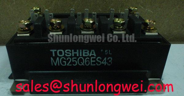
For a precision stepper or BLDC motor servo motion actuator, evaluate the MG25Q6ES43 IGBT module against the existing inverter topology, control method, and protection circuit. Its 25 A rating is one input to that assessment. The integration review should also examine operating temperature, switching losses, load transients, and available cooling using the applicable device characteristics and the machine’s actual duty profile.
Benchtop Waveform Tuning: Mitigating Stress via Separating Driver Return from Main Current on MG25Q6ES43
Trace the driver return connection from the schematic to the physical emitter connection before adjusting gate resistance or switching commands. As a Design Consideration, shared inductance between the load current path and the gate return can introduce a voltage disturbance during rapid current changes. Keep the driver return away from unnecessary load current paths, and assess the resulting gate voltage at the device connection rather than relying solely on the driver board output.
A dedicated auxiliary emitter connection should be used as a gate reference only when the manufacturer’s terminal diagram identifies that function. Do not assign a Kelvin emitter role from terminal position or appearance. Where the documented assembly uses a shared emitter connection, examine the external return routing and connection point for avoidable common impedance. The practical objective is a stable gate reference within the terminal arrangement the device actually provides.
Capture gate-to-emitter voltage and the relevant power switching waveform with suitable probes, controlled lead placement, and repeatable operating conditions. As an Engineering Recommendation, compare ringing, turn-off overshoot, and unintended gate excursions before changing the drive network. Adjustments should follow the approved driver design and then be checked across the required operating conditions. A cleaner trace at a convenient board test point can conceal a disturbance at the module terminals.
Inspect the thermal interface whenever the module is removed. Check heatsink flatness and cleanliness, mounting contact, and the condition of the specified thermal material; use the equipment’s assembly procedure for renewal and tightening. The Advanced Thermal Management Revolution provides background on thermal management approaches, while the module’s own mounting instructions govern its installation.
Maintenance Note: Trend terminal temperature rise and inspect cooling airflow during scheduled service so deteriorating connections or blocked passages receive attention before recommissioning.
As a Design Consideration, set cleaning and interface inspection intervals from cabinet contamination, operating temperature trends, and maintenance history. Examine fan performance, filter loading, and evidence of moisture before restarting equipment after a cold shutdown. The physical background described in thermal shock helps explain why abrupt temperature changes deserve attention, but it does not establish a qualification result for this module. Where condensation is present, follow the equipment’s drying and insulation inspection procedure before restoring power.