Content last revised on October 15, 2026
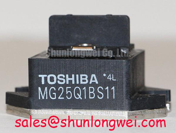
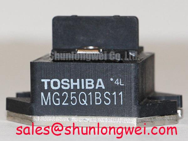
Preventing Spurious Faults: Differential Gate Source Loop Routing Guidelines for MG25Q1BS11
Separate the auxiliary emitter return used by the gate driver from the main high current emitter path so the driver does not sense voltage created by load current. Shared copper can introduce emitter mutual coupling, and the resulting feedback may appear as intermittent gate ringing, false desaturation activity, or inconsistent switching between identical power legs.
As a Design Consideration, route the gate signal and its dedicated return as a compact differential loop from the driver output to the module terminals. Keep this loop away from the commutation path, rectifier charging path, and high dv/dt collector nodes. The main emitter conductor should carry power current directly to the DC link or phase connection, while the auxiliary return should remain a quiet reference for the gate driver. Do not join both returns at an arbitrary chassis point or through a long shared copper track.
During field troubleshooting, inspect the driver board connector, gate resistor joints, auxiliary emitter contact, and any flexible cable used between the control board and power stage. A continuity check confirms the intended route but cannot reveal voltage developed across a shared trace during switching. For a recurring gate fault, use a properly referenced differential probe and compare the gate to its local emitter reference at the module, not to a distant control ground. Check whether the disturbance follows one phase or appears across all phases; this comparison helps separate local routing problems from common driver or DC link disturbances.
When the module is installed in a servo amplifier, designers should minimize parasitic loop area while preserving creepage, clearance, service access, and mechanical strain relief. The actual spacing and conductor geometry remain system determined by working voltage, insulation construction, pollution environment, and applicable equipment standards. A long motor cable can also return reflected switching energy to the inverter, so the cable termination, common mode path, and output filter should be reviewed together with the gate loop rather than treated as an isolated module issue.
MG25Q1BS11 Circuit Protection and Reliability: Calibrating SCSOA Overcurrent Protection
Short circuit protection must react before the IGBT remains exposed to destructive collector current and inductive overvoltage. A practical protection architecture separates the fast detection decision from the controlled turn off action. Type I and Type II short circuit events should be characterized with the actual gate driver, current sensor or desaturation circuit, bus structure, and load emulator. A controller response target inside 10 µs may be used as an Engineering Recommendation for protection development, but it is not an official MG25Q1BS11 switching or short circuit rating stated in the supplied product data.
The first turn off stage should remove the commanded gate drive promptly while avoiding an unnecessarily abrupt current interruption. A second soft turn off stage can then control the remaining current transition and reduce inductive voltage stress. The gate driver must be checked for blanking behavior, desaturation diode recovery, propagation delay, isolation barrier response, and fault latch timing. A protection circuit that works on a resistive bench load can respond differently with a motor phase, a long cable, or a partially charged DC link.
Parallel module evaluation requires symmetrical busbar geometry and closely matched gate drive paths. Equal conductor length, similar contact resistance, and consistent thermal mounting support more predictable static current sharing. The positive temperature coefficient of VCE(sat) can assist current balancing under suitable operating conditions, but it does not correct major asymmetry in bus inductance, gate timing, emitter impedance, or cooling. Measure each parallel branch during controlled switching tests and review both current and collector emitter voltage rather than relying on static continuity checks.
For CNC and robotics servo repairs, verify the fault path from current detection to PWM shutdown with the motor disconnected and the DC link safely controlled. Confirm that a fault signal cannot be cleared by electrical noise, that the isolation barrier remains stable during common mode transients, and that the driver supply does not collapse into an uncontrolled gate state. ⚠️ Field Alert: Never connect or remove gate and auxiliary emitter wiring while the DC link or driver supply is energized.
The MG30G6EL2 may be reviewed as a separate Toshiba module option during a controlled cross reference exercise, but voltage, current, terminal layout, gate characteristics, and protection behavior must be matched against the original servo amplifier design before any substitution decision.
MG25Q1BS11 Thermal Electrical Optimization: Evaluating Thermal Capacitance and Heat Sink Response
For pulsed overloads, junction temperature is governed by both instantaneous power and the thermal history stored in the semiconductor package, interface material, base structure, and heat sink. A steady state heat sink calculation can miss a short overload that produces a sharp junction temperature rise before the case temperature changes significantly. Use the manufacturer thermal network when available, then combine its transient impedance response with measured switching and conduction losses from the actual servo waveform.
As an Engineering Calculation, a multi RC thermal model represents the junction to case response as several time dependent thermal paths rather than one fixed resistance. The calculated junction temperature should be compared with the permitted operating boundary after accounting for pulse width, repetition rate, starting case temperature, and the cooling system response. The result is meaningful only when the power loss waveform, duty cycle, mounting pressure, interface condition, and heat sink airflow reflect the repaired equipment.
Inspect the mounting surface for burrs, uneven contact, contamination, and mechanical distortion. Apply the selected thermal interface material consistently according to its supplier process guidance. The general behavior of thermal interface materials, including the difference between phase change materials and thermal grease, is discussed in this Thermal Interface Material reference with additional material packaging context. The module’s thermal result remains installation dependent, not a standalone property of the part number.
Substrate selection and heat spreading can influence transient response, contact temperature, and long term mechanical stability. Engineers comparing power stage constructions can consult The Advanced Thermal Management Revolution and the Aluminum Nitride substrate reference for general packaging background. These references support technology evaluation and do not establish an MG25Q1BS11 specific material construction.
After installation, compare phase current, switching edge behavior, case temperature, and fault timing under the original motor acceleration profile. A long motor cable, insufficient output filtering, rectifier harmonic current, or bootstrap supply ripple can increase stress seen by the inverter even when the module’s static measurements appear normal. The repaired servo should therefore be validated as a complete power stage, with the MG25Q1BS11 operated inside its documented electrical and thermal boundaries.