Content last revised on September 16, 2026
MIG25Q901H Thermal-Electrical Optimization: PCB Symmetry Considerations for Practical Tuning
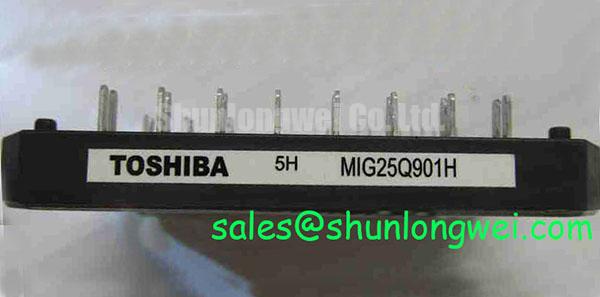
Before reconnecting a failed drive, isolate the DC link, inspect the module terminals and surrounding PCB for heat discoloration or loose hardware, then confirm that the equipment nameplate matches the MIG25Q901H electrical boundary of 600 V VCES and a 25 A rated collector current under the specified conditions. These values are Official Datasheet Specifications supplied for this Toshiba IGBT module and should be treated as device limits rather than system operating targets.
The supplied specification identifies a typical VCE(sat) of 2.5 V and a specified collector dissipation rating of 80 W. In a motor-drive repair, these figures give the maintenance engineer a defined starting point for reviewing conduction-loss behavior and thermal path condition, but they do not replace measurement of the actual switching waveform, load profile, heat sink performance, or enclosure airflow.
Design Consideration: PCB symmetry matters whenever the drive topology uses corresponding switching paths. Keep each gate-drive return path associated with its intended emitter reference and avoid allowing high-current emitter routing to become the reference path for a sensitive control loop. Shared impedance in a power return can alter the apparent gate-emitter voltage during fast current transitions. That condition can appear as uneven switching behavior, ringing, unexpected protection events, or differing device temperatures even when the control command looks balanced at the controller output.
For field troubleshooting, examine the physical route from gate-driver output to the module connection, the return route, the DC-link connection, and the location of current-sense wiring. A comparison against a known-good phase or channel can help isolate a layout, connector, driver, or measurement-reference problem. Use properly referenced differential probing when observing switching nodes; a ground lead placed in the wrong location can create a misleading waveform.
When integrating the MIG25Q901H into a heavy-duty variable frequency AC motor drive, system engineers should minimize parasitic loop inductance to suppress turn-off overshoot and validate peak voltage margin against the DC-link voltage during controlled switching tests. The module's 600 V rating is an official device specification, while PCB geometry, snubber selection, gate resistance, switching speed, and permissible overshoot remain system-determined design decisions.
Do not infer internal terminal arrangement, auxiliary-emitter availability, or gate-driver requirements from the model name alone. The installer should verify the terminal map, mechanical drawing, and driver interface against the original equipment documentation before placing the unit into service. This is especially important where a repaired inverter board has undergone prior wiring or PCB rework.
Maintenance Note: Monitor terminal and heat-sink contact temperature during loaded commissioning, then inspect the cooling air path for dust accumulation and restricted flow before returning the drive to continuous duty.
MIG25Q901H Circuit Protection & Reliability: Calibrating Desaturation Detection
The MIG25Q901H is specified with integrated OC, UV, and OT protection functions. OC denotes over-current protection, UV denotes under-voltage protection, and OT denotes over-temperature protection in the supplied official product data. Their presence does not define the external drive-control architecture, trip threshold, timing sequence, reset behavior, or the response of the complete inverter after a fault. Those operating details must be verified from the original Toshiba documentation and the host equipment design.
In a repair assessment, start by determining whether the controller is reporting an over-current, under-voltage, or thermal-related condition, then verify the associated sensing paths and gate-driver supply rails with the appropriate isolated instrumentation. A fault indication may arise from a genuine power-stage event, but it can also be associated with a connector issue, contaminated board surface, degraded cooling path, control-board supply instability, or an incorrect measurement reference. Avoid treating one symptom as proof of one root cause.
Desaturation monitoring is a Design Consideration for an externally controlled IGBT gate-drive arrangement. Its purpose is to observe collector-emitter behavior while the switching device is commanded on, allowing the control system to recognize an abnormal conduction condition before the available short-circuit operating boundary is exceeded. The exact detection threshold, blanking interval, filter behavior, and reaction timing are determined by the driver circuit, topology, bus voltage, load inductance, and validated system test results. They are not stated as official characteristics of this module in the supplied data.
Where an inverter controller uses a staged turn-off response, engineers should review whether the controlled gate discharge path limits the inductive voltage excursion while reliably ending current conduction. A very abrupt response can increase voltage stress in a layout with substantial loop inductance, while an excessively slow response can extend electrical and thermal stress. Oscilloscope captures taken with a known-safe setup are more useful than assumptions when evaluating that tradeoff.
The typical 2.5 V VCE(sat) value is a device characteristic, not a universal desaturation threshold. It should not be copied into a protection circuit as a fixed trip setting without reference to the relevant operating conditions and original documentation. Collector-emitter voltage during operation changes with current, junction temperature, dynamic switching state, and measurement position.
For long-term preventive maintenance, inspect gate-driver supply capacitors, fault-return routing, interlock wiring, and heat-sink cleanliness during scheduled downtime. A controlled re-energization sequence with the motor mechanically unloaded, where the equipment procedure permits it, can provide a safer setting for confirming command behavior and protection reporting.
Field Diagnostics & Commissioning: Insulation Barrier Integrity in MIG25Q901H Topologies
During commissioning, inspect insulation barriers, board spacing, protective covers, cable glands, and contamination around the power stage before applying high voltage. The supplied data does not state a reinforced-isolation rating, common-mode transient immunity rating, insulation test voltage, pollution-degree rating, or altitude capability for the MIG25Q901H. Those characteristics must not be assumed from its 600 V collector-emitter rating.
Design Consideration: galvanic isolation between control circuitry and the power stage is established by the complete drive architecture, which can include isolated gate drivers, isolated sensing circuits, isolated power supplies, PCB construction, clearance and creepage distances, and enclosure design. Where an equipment safety procedure requires an insulation-resistance or dielectric test, use the original equipment test method and test limits. A generic test level can damage sensitive connected electronics or provide a result that does not reflect the assembled system condition.
Common-mode transient behavior should be investigated at the driver interface, command signals, sensing network, cable screens, and power-return paths. Spurious gate pulses or unstable fault signals may indicate a reference-coupling, shielding, routing, or driver-supply issue. Verify the relevant signal path with suitable isolated measurement equipment and compare the result against an equivalent healthy channel where available.
Moisture, conductive dust, and residue can reduce the reliability of the complete inverter assembly even when the IGBT module itself shows no visible damage. Equipment teams should inspect for condensation risk after cold starts, confirm that cabinet heaters or ventilation arrangements operate as intended, and allow the assembly to reach an appropriate stable condition before high-load testing. Cleaning methods and materials should follow the equipment manufacturer's service guidance so that labels, connectors, coatings, and insulation surfaces are not compromised.
The Comparative Tracking Index is a material-property concept used when evaluating insulating surfaces in electrical assemblies. It is not an official CTI declaration for the MIG25Q901H. In the same way, the Restriction of Hazardous Substances Directive describes a regulatory framework; no material-compliance claim for this specific module should be made without applicable manufacturer documentation.
For broader measurement discipline, isolation checks, and evidence-led fault analysis, the Field Engineer’s Handbook provides related technical reference material. Apply any procedure within the voltage ratings, isolation requirements, and lockout practices of the installed equipment.
MIG25Q901H Thermal-Electrical Optimization: Thermal Feedback Practical Tuning
Start thermal troubleshooting at the module-to-heat-sink interface. Remove accumulated debris from the heat sink, confirm that the mounting surface is clean and flat within the equipment service requirements, and examine the thermal interface material for drying, displacement, contamination, or incomplete contact. The 80 W collector dissipation figure is an Official Datasheet Specification, but actual temperature rise depends on the installed heat sink, airflow, mounting condition, switching losses, conduction losses, ambient temperature, and motor-drive duty cycle.
The stated typical VCE(sat) of 2.5 V can be useful when interpreting controlled static measurements, provided the technician observes the applicable measurement conditions from the official documentation. It should not be used as a standalone health verdict. Temperature, current, wiring resistance, instrument connection points, and pulsed versus steady-state operation all affect the observed result.
Design Consideration: in parallel or corresponding switching paths, static current distribution and dynamic switching distribution are separate issues. Thermal feedback associated with on-state voltage behavior can influence steady-state sharing, while gate-loop symmetry, control timing, power-loop coupling, and driver behavior influence transient sharing. When integrating or repairing a drive, engineers should review both areas rather than relying on a single current measurement or a single thermal image.
Use a repeatable commissioning sequence. Establish baseline temperatures and waveforms under a controlled load condition, compare corresponding channels, then review cooling performance after the unit has reached normal operating temperature. If imbalance appears, inspect gate wiring, connector seating, driver outputs, current-sense references, DC-link connections, and heat-sink contact before assigning the issue to the module. This approach preserves evidence and reduces unnecessary replacement decisions.
The integrated OC, UV, and OT functions are relevant to protection review, but they do not eliminate the need for cabinet maintenance. Periodic checks of fan operation, filter condition, thermal-interface aging, terminal tightness, and condensation control help maintain stable operating conditions around the module. Any mounting torque, thermal compound thickness, electrical clearance, gate-drive value, or switching-frequency setting must follow the original equipment documentation or a system-specific validated engineering procedure; none of these values are supplied as official MIG25Q901H parameters here.
For an alternative module evaluation, MG150Q1JS40 is a separate product page that can be reviewed against the original drive's electrical, mechanical, protection, and thermal requirements. Its model designation alone does not establish direct interchangeability with the MIG25Q901H.