Content last revised on October 12, 2026
MG300H1UL1 Thermal-Electrical Optimization: Turn-Off di/dt Induced V_peak Clamping and Practical Tuning
I check the collector-to-emitter turn-off waveform against the DC-link measurement before changing gate resistance or adding a snubber around the MG300H1UL1. A useful capture includes collector current and gate-to-emitter voltage, with probes referenced to the relevant device terminals. Long probe connections can introduce ringing that resembles a power-circuit problem. Establish the measurement arrangement before interpreting a narrow voltage peak as evidence of inadequate clamping.
The Toshiba module carries supplied official ratings of 600.0 V and 300.0 A. Those figures establish its electrical class, while the associated datasheet conditions govern their use. Design Consideration: Evaluate operating current alongside switching losses, conduction losses, cooling performance and transient stress. A replacement assessment should distinguish continuous operation from brief overload conditions rather than treating the current rating as an unconditional operating allowance.
Engineering Calculation: A first-order turn-off estimate expresses peak collector voltage as the DC-link voltage plus stray commutation inductance multiplied by the magnitude of current fall rate. This explains why a faster current transition or a longer current loop can increase overshoot. It does not include every contribution from diode recovery, distributed capacitance or ringing, so measured switching behavior remains the basis for assessing the actual voltage margin.
Design Consideration: Keep outgoing and returning commutation paths close together, and avoid asymmetrical connections that introduce unequal impedance between switching positions. Planar busbars can reduce loop area, but their geometry must also satisfy the equipment’s insulation coordination, mechanical tolerances and terminal access requirements. Evaluate the assembled connections, including capacitor leads and joints, rather than judging inductance from the busbar alone.
A snubber should address the measured transient mechanism. Its capacitance, pulse-current capability, voltage rating and damping arrangement depend on the energy being diverted and the repetition rate. Positioning it near the relevant commutation loop can reduce connection inductance; adding capacitance through a long lead may leave the initial peak largely unchanged. Check capacitor heating and any damping-element dissipation during repeated operation, not just the appearance of a single waveform.
Engineering Recommendation: Keep the commutation busbar paths geometrically balanced, then validate turn-off voltage margin with a controlled double-pulse test before increasing operating stress.
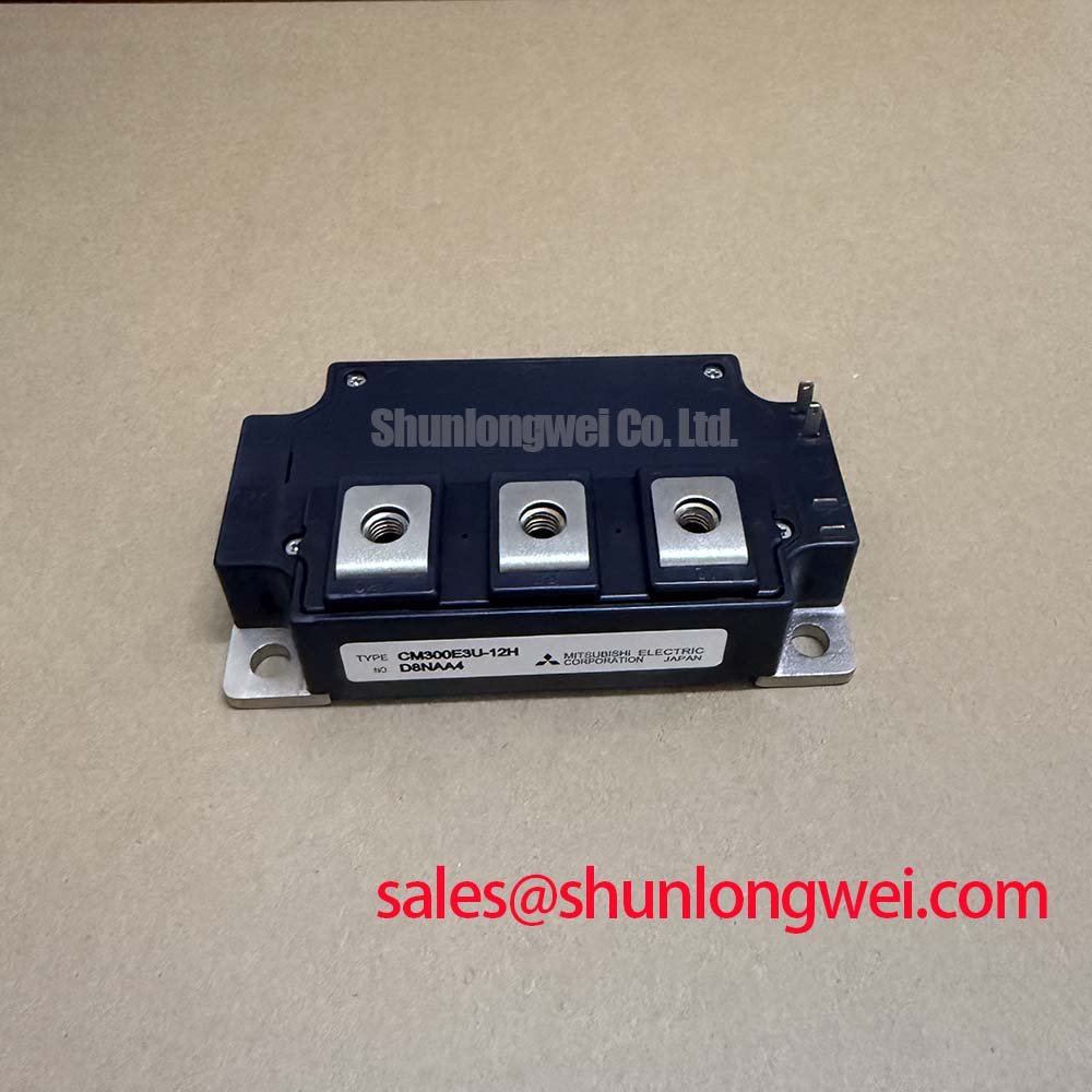
When evaluating hardware alternatives, the CM300E2U-12F belongs in a documented compatibility comparison, not an assumed direct-replacement decision. Compare internal circuit arrangement, terminal functions, mounting interfaces, gate requirements and switching characteristics. Matching headline voltage and current ratings alone does not establish electrical or mechanical interchangeability.
Field Diagnostics & Commissioning: Optocoupler vs Digital Coreless Transformer in MG300H1UL1 Topologies
Capture the driver input and its gate-side output together when investigating an unexplained switching pulse. A disturbance that appears only after the power stage starts commutating directs attention toward common-mode coupling, driver supply movement or gate-loop pickup. A disturbance already present at the command input requires examination of the controller path. Neither observation, by itself, proves that the isolation component has failed.
Design Consideration: An optocoupler and a digital isolator using a coreless transformer are system-level driver choices, not established internal features of the MG300H1UL1. Compare propagation delay, channel timing variation, output behavior during supply interruption and immunity to the common-mode transients present in the equipment. The relevant comparison is the complete driver channel, including its isolated supply and output stage, rather than the isolator technology name.
Isolation withstand voltage, working voltage and reinforced-insulation qualification describe different requirements. Evaluate the driver component documentation together with PCB creepage, clearance, enclosure conditions and the applicable equipment standard. A component-level insulation claim does not establish compliance of the finished assembly. Similarly, common-mode transient immunity should be assessed against measured switching conditions and the manufacturer’s stated test conditions, without assigning an unsupported threshold to this module.
For a floating driver supplied through a bootstrap circuit, check supply behavior through the longest commanded on-time and the available recharge intervals. Design Consideration: Bootstrap capacitance selection depends on gate-charge demand, driver consumption, leakage and allowable supply movement. The charging diode’s recovery behavior and the charging-loop impedance can affect disturbance levels. These are properties of the external driver implementation; they are not evidence that the MG300H1UL1 includes a bootstrap supply.
Compare local driver supply voltage with gate-to-emitter voltage during switching. A collapsing supply and a transient gate disturbance call for different corrective actions. Inspect return routing and coupling paths before changing the isolator. Low-voltage control traces should not share unnecessary impedance with high-current commutation paths, and probe placement should distinguish actual gate movement from movement of the measurement reference.
The background discussion in Power Inverter Topologies and Pulse-Width Modulation helps distinguish bridge switching behavior from higher-level control behavior. The separate treatment of droop control concerns load sharing and regulation; it is not a gate-driver isolation specification. During commissioning, retain that distinction so a supervisory control adjustment is not mistaken for a remedy to switching-edge interference.
MG300H1UL1 Operational Boundaries: Evaluating and Suppressing C_res Induced Gate Voltage Spike Limits
Measure the off-state gate-to-emitter waveform while the complementary switching position commutates, using a reference close to the device’s gate-return connection. A transient rise can result from collector-to-gate capacitive coupling, shared return inductance or driver-output impedance. Check its timing against collector voltage and current before attributing additional current to unintended turn-on.
Design Consideration: Reverse-transfer capacitance couples a changing collector voltage into the gate circuit. The resulting gate disturbance depends on the voltage transition, device capacitance behavior and impedance of the available discharge path. A lower-impedance turn-off path can help control this disturbance, but the complete loop matters: a capable driver connected through long traces can still leave substantial voltage movement at the module terminals.
Route gate and gate-return conductors together and separate their return path from load-current wiring wherever the verified terminal arrangement permits. If the module drawing identifies a dedicated auxiliary emitter connection, assess it as the driver reference according to that drawing. Do not assign Kelvin-emitter functionality to an unidentified terminal. The objective is to reduce shared impedance without inventing a connection that the package does not provide.
An active Miller clamp can provide a local discharge path after turn-off, subject to the driver’s clamp activation behavior and connection arrangement. Negative gate bias is another system-level option, but its magnitude must remain within the device’s gate limits and the driver’s output capability, including transient excursions. Select either approach from measured behavior and documented limits rather than prescribing a universal bias voltage.
Ground-bounce investigation benefits from separating differential gate voltage from common-mode movement of the driver circuit. Review isolated-supply capacitance, control-cable routing and any shield termination against the equipment grounding scheme. Changing shield connections without understanding the return paths can relocate interference instead of removing it. Compare waveforms under the same load and probe arrangement so the effect of each change remains identifiable.
Dead time and protection timing also influence apparent cross-conduction. Inspect command overlap, driver delay variation and fault-response behavior alongside the analog gate waveforms. A current spike can contain diode-recovery current or measurement artifacts as well as unwanted transistor conduction. Record the conditions under which it occurs, then adjust only the circuit feature supported by that evidence.
For an industrial inverter welder or medium-frequency induction-heating power supply, designers may evaluate the MG300H1UL1 against the existing switching topology, operating frequency, gate-drive interface and thermal assembly. This is a compatibility assessment, not a declaration of suitability for every machine in those categories. The original power-stage circuit and operating envelope should remain the reference for repair decisions.
MG300H1UL1 Thermal-Electrical Optimization: Sizing Braking Resistors and Chopper Transistors for Practical Tuning
Trace the regenerative-energy path on the equipment schematic before assigning the MG300H1UL1 a braking-chopper role. In a motor-drive system, deceleration can return energy to the DC link; a chopper and resistor provide one possible dissipation path. That function belongs to the equipment topology and does not establish an internal braking circuit within this Toshiba module.
Design Consideration: Resistor evaluation starts with the mechanical energy returned during the actual braking event, the required stopping profile and the frequency of repeated events. Account for energy dissipated elsewhere in the system rather than assuming the entire mechanical energy reaches the resistor. Its pulse-energy capability, average thermal loading, enclosure ventilation and permitted surface temperature all affect the assessment.
The chopper transistor requires a separate review of current waveform, switching loss, conduction loss and fault exposure. A resistor that satisfies average-power requirements can still place excessive pulse stress on the switching device. Conversely, a transistor with adequate current capability does not make the resistor’s thermal duty acceptable. Coordinate the chopper turn-on behavior, DC-link monitoring and protective response with the equipment’s documented operating limits.
During controlled commissioning, observe DC-link voltage, chopper current and resistor temperature through both an isolated braking event and the intended repetition pattern. A rising bus voltage may reflect delayed chopper activation, interrupted resistor wiring, control restrictions or energy beyond the dissipation path’s capacity. Use the synchronized measurements to distinguish these possibilities rather than replacing the power module solely because the drive reports an overvoltage event.
Thermal integration should include the module-to-heatsink interface, mounting condition, airflow or coolant performance, and heat transferred from nearby components. The article The Advanced Thermal Management Revolution provides broader thermal-management context; it does not identify the MG300H1UL1’s internal substrate construction or establish a service-life guarantee. Apply the module’s own assembly requirements when assessing the installed thermal path.
For a repair handover, retain the terminal comparison, driver settings, switching captures and braking-duty observations with the equipment record. The acceptance check should demonstrate that the intended stopping sequence stays within the documented electrical and thermal limits, that protection responds correctly to an interrupted dissipation path, and that repeated operation does not produce progressive temperature rise beyond the approved operating envelope.