Content last revised on September 10, 2026
Toshiba MG30J6ES50 600V 30A 6-Pack IGBT Module for Industrial Motor Control
The Toshiba MG30J6ES50 is an integrated 6-pack IGBT module designed to optimize power density and minimize switching losses in compact industrial inverters. Operating at a breakdown rating of 600V and a continuous collector current of 30A, this silicon N-channel device integrates six IGBT switches and antiparallel free-wheeling diodes into a single isolated package. Key specifications include: 600V | 30A | N-Channel 6-Pack Bridge. Key benefits include simplified three-phase circuit assembly and minimal parasitic loop inductance. By housing a complete inverter bridge in one module, it eliminates the wiring complexity and stray inductance inherent in discrete implementations. What is the primary benefit of the MG30J6ES50 integrated 6-pack module? It reduces PCB trace parasitics and simplifies 3-phase inverter layout. For 600V compact motor drives prioritizing reduced component count and fast switching, the Toshiba MG30J6ES50 30A module is the optimal choice.
Application Scenarios & Value
Achieving High Power Density in Compact 600V Motor Drives
Engineers often face significant spatial and thermal constraints when designing compact Variable Frequency Drives (VFDs) for low-to-medium power automation systems. In small industrial pumps, conveyor belt actuators, and HVAC fan controls operating from standard 200V to 400V AC lines, layout real estate on the control PCB is extremely tight. Discrete switching configurations require six individual transistors and six external diodes, leading to expansive trace routings that introduce unwanted parasitic inductance and electromagnetic interference (EMI).
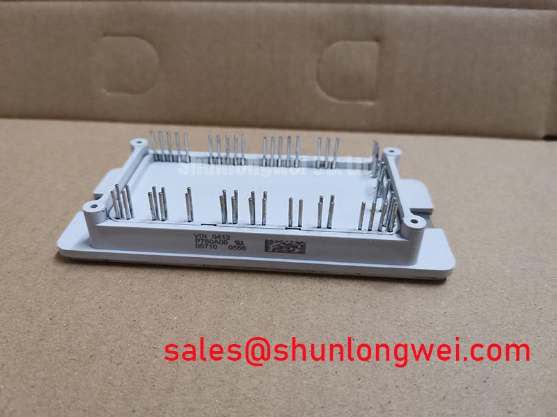
The Toshiba MG30J6ES50 resolves this layout challenge through its all-in-one 6-pack bridge configuration. By housing six N-channel IGBT elements with matched antiparallel diodes in a 21-pin flange mount package, it allows designers to directly connect the DC-bus input to a single component, driving three-phase AC outputs with minimal PCB footprint. Understanding the underlying voltage-controlled switching principle allows engineers to optimize gate driver circuitry for maximum system efficiency. For power systems requiring a higher continuous current capability under similar 600V voltage constraints, the related MG75J6ES50 offers an elevated 75A rating to accommodate heavier mechanical loads.
Technical Deep Dive
Optimizing 6-Pack Integration to Suppress Parasitic Inductance
The internal architecture of the MG30J6ES50 combines high-speed silicon IGBT dies bonded to an electrically isolated copper substrate. Discrete component layouts are like a web of winding suburban roads where traffic slows at every turn; the integrated substrate of the MG30J6ES50 acts like an express highway, channeling current through ultra-short internal bond wires to minimize parasitic inductance during rapid commutation. This minimized loop inductance suppresses voltage spikes during turn-off transients, protecting the die without requiring excessively heavy snubber circuitry.
Thermal management and electrical isolation are equally critical in high-density power stages. Operating an unisolated switching stage without proper thermal separation is like running a precise race on uneven terrain; the isolated metal baseplate of the MG30J6ES50 ensures thermal energy glides smoothly to the heatsink without electrical noise disrupting control logic. Featuring a nominal turn-on time ton of 500 ns and turn-off time toff of 550 ns, alongside an isolation rating of 2500V AC, the module provides low switching losses while maintaining high galvanic safety. Designing robust system architectures requires careful coordination between IGBT gate drive and thermal management strategies to maintain junction temperatures well within safe limits.
Key Parameter Overview
Decoding Specs for High-Efficiency Switching and Thermal Reliability
Evaluating the electrical parameters of the MG30J6ES50 provides insight into its performance boundaries and circuit compatibility.
| Parameter | Symbol | Specification Value | Engineering Impact |
|---|---|---|---|
| Collector-Emitter Voltage | VCES | 600V | Provides sufficient voltage headroom for 200V–400V AC line rectified DC buses. |
| Continuous Collector Current | IC | 30A | Delivers continuous power capability suitable for motor drives up to several kilowatts. |
| Collector-Emitter Saturation Voltage | VCE(sat) | 2.1V (typ) | Low conduction voltage drop reduces steady-state thermal dissipation across all six switches. |
| Turn-On Time | ton | 500 ns (nom) | Fast turn-on transitions minimize switching energy losses during PWM cycles. |
| Turn-Off Time | toff | 550 ns (nom) | Short turn-off delay enables higher switching frequencies and smaller filter components. |
| Isolation Voltage | VISOL | 2500V AC (1 min) | Allows direct mounting on a shared heatsink while meeting safety isolation standards. |
| Circuit Configuration | Structure | Bridge, 6 Elements | Integrates a full 3-phase inverter bridge in one 21-pin package to reduce assembly time. |
Download the MG30J6ES50 datasheet for detailed specifications and performance curves: Download Datasheet.
Frequently Asked Questions
Engineering Answers for 600V 30A Inverter Implementation
How does the 6-in-1 topology of the MG30J6ES50 benefit three-phase motor inverter designs?
The integrated 6-pack topology places all six IGBTs and co-packaged freewheeling diodes on a single isolated substrate. This arrangement eliminates six discrete packages, slashes PCB assembly complexity, and minimizes parasitic interconnect inductance, resulting in cleaner switching waveforms and improved overall inverter power density.
What gate drive considerations are recommended for switching the MG30J6ES50 safely?
A gate drive voltage VGE of +15V is recommended to achieve the low published VCE(sat) values. To prevent parasitic Miller turn-on caused by high dv/dt transients during fast switching, utilizing a gate driver with an integrated active Miller clamp or applying a negative off-bias (such as -5V to -10V) ensures robust gate noise immunity.
Why is isolation voltage rating crucial when mounting the MG30J6ES50 to a shared heatsink?
The internal isolation layer provides 2500V AC insulation between the internal live semiconductor dies and the copper baseplate. This allows the module to be bolted directly onto a common aluminum heatsink without requiring external mica pads or isolators, maximizing thermal conductivity while maintaining strict electrical isolation safety.
How do the switching speed parameters (ton and toff) affect thermal design in PWM inverters?
With a typical ton of 500 ns and toff of 550 ns, the MG30J6ES50 exhibits low turn-on and turn-off switching energy consumption. This fast response allows operating at higher pulse-width modulation (PWM) frequencies in the 10 kHz to 20 kHz range, enabling engineers to reduce the physical size of output filter inductors without exceeding thermal dissipation limits.
What thermal protection practices prevent destructive thermal runaway in 30A IGBT modules?
Maintaining junction temperatures within ratings requires high-quality thermal interface material (TIM) applied uniformly between the baseplate and heatsink. In addition, evaluating the system using thermal management and voltage rating selection protocols and staying strictly inside the module's Safe Operating Area (SOA) under peak load conditions ensures long-term operational integrity.
Field experience shows that matching the gate resistor value to the specific switching frequency of the MG30J6ES50 provides an optimal balance between dv/dt noise control and switching loss minimization in industrial motor drives.