Content last revised on September 10, 2026
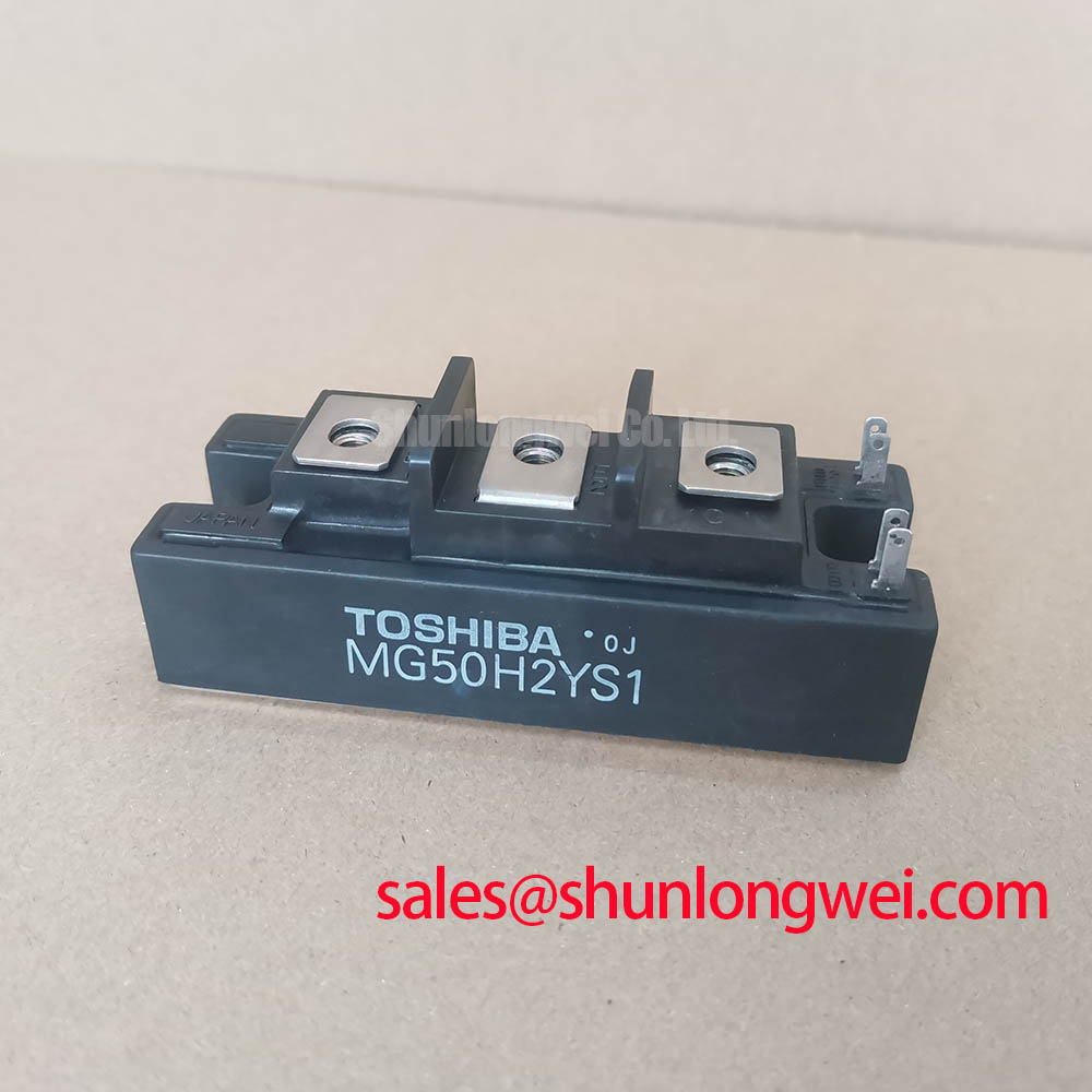
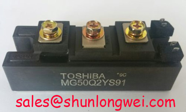
MG50Q2YS91 Toshiba 1200V 50A Dual IGBT Module
An Engineer's Overview of the MG50Q2YS91 IGBT Module
The Toshiba MG50Q2YS91 is a dual Silicon N-Channel IGBT module engineered for reliability and efficiency in medium-power switching applications. It integrates a complete half-bridge circuit into a single, robust package, offering key specifications of 1200V collector-emitter voltage and a 50A continuous collector current. This strategic integration simplifies the design of inverter legs and reduces overall component count. A critical performance metric is its maximum collector-emitter saturation voltage (VCE(sat)) of 2.7V at its nominal current, which is pivotal for managing conduction losses. For designers of sub-15kW Variable Frequency Drive (VFD) systems requiring a cost-effective and reliable 1200V half-bridge solution, the MG50Q2YS91 is a technically sound choice.
Application Scenarios & Value
Enabling Robust Performance in Industrial Drives and Power Supplies
The MG50Q2YS91 is optimized for power conversion systems where efficiency and durability are critical decision factors. Its 1200V blocking voltage provides the necessary safety margin for applications operating on 380V to 480V AC lines, making it a staple component in industrial automation. What is the primary benefit of its integrated half-bridge design? It significantly reduces stray inductance and simplifies the gate drive layout compared to using discrete components, leading to cleaner switching and improved system reliability.
In a high-fidelity engineering scenario, consider the design of a 10kW motor drive for a conveyor system. The 50A current rating of the MG50Q2YS91 comfortably handles the continuous load, while its peak current capability (100A for 1ms) accommodates the initial motor startup surge. The module's VCE(sat) of 2.7V max directly impacts the thermal design; it dictates the level of heat generated during operation. Think of VCE(sat) as the "toll" the current pays to pass through the switch; a lower toll means less energy is wasted as heat, allowing for a smaller, more cost-effective heatsink. This makes the MG50Q2YS91 a pragmatic choice for power stages in servo drives, welding power supplies, and uninterruptible power supplies (UPS). For systems requiring higher current handling capabilities, the related CM100DY-24H offers a higher rating of 100A at the same 1200V classification.
Key Parameter Overview
A Data-Driven Look at Electrical and Thermal Characteristics
The performance of the MG50Q2YS91 is defined by its electrical and thermal specifications. The following table summarizes the key parameters derived from the official datasheet, grouped by function to aid in engineering evaluation.
| Characteristic | Symbol | Test Condition | Min | Typ | Max | Unit |
|---|---|---|---|---|---|---|
| Maximum Ratings (Ta = 25°C) | ||||||
| Collector-Emitter Voltage | VCES | - | - | 1200 | V | |
| Gate-Emitter Voltage | VGES | - | - | ±20 | V | |
| Collector Current (DC) | IC | - | - | 50 | A | |
| Collector Current (1ms) | ICP | - | - | 100 | A | |
| Collector Power Dissipation | PC | Tc = 25°C | - | - | 400 | W |
| Junction Temperature | Tj | -40 | - | 150 | °C | |
| Electrical Characteristics (Tj = 25°C) | ||||||
| Collector-Emitter Saturation Voltage | VCE(sat) | IC = 50A, VGE = 15V | - | 2.2 | 2.7 | V |
| Gate-Emitter Cutoff Voltage | VGE(th) | IC = 50mA, VCE = 5V | 3.0 | - | 6.0 | V |
| Collector Cutoff Current | ICES | VCE = 1200V, VGE = 0 | - | - | 1.0 | mA |
| Switching Characteristics (Inductive Load) | ||||||
| Turn-on Time | ton | VCC = 600V, IC = 50A, RG = 47Ω | - | 0.4 | 0.6 | µs |
| Turn-off Time | toff | - | 0.8 | 1.2 | µs | |
| Reverse Recovery Time (Diode) | trr | - | 0.15 | 0.25 | µs | |
| Thermal Characteristics | ||||||
| Thermal Resistance (IGBT) | Rth(j-c) | Junction to Case | - | - | 0.4 | °C/W |
| Thermal Resistance (Diode) | Rth(j-c) | Junction to Case | - | - | 1.0 | °C/W |
Download the MG50Q2YS91 datasheet for detailed specifications and performance curves.
Technical Deep Dive
Inside the MG50Q2YS91: Balancing Conduction and Switching Performance
The MG50Q2YS91 is built using Toshiba's established N-channel IGBT technology, which provides a robust and reliable switching platform. A key aspect of its design is the trade-off between conduction losses, primarily governed by VCE(sat), and switching losses (Eon and Eoff). With a typical VCE(sat) of 2.2V and a maximum of 2.7V, this module is engineered to keep heat dissipation manageable during the 'on' state. This characteristic is crucial for applications with high duty cycles, such as motor control and power supplies. The thermal resistance, Rth(j-c), of 0.4 °C/W per IGBT is a direct measure of how effectively heat can be transferred from the silicon die to the module's baseplate. Lowering this value is like widening a highway for heat to escape; it ensures the junction temperature stays within safe limits, which is fundamental for long-term operational reliability. What is the impact of its switching speed? With a typical turn-off time (toff) of 0.8µs, the module is well-suited for Pulse Width Modulation (PWM) frequencies commonly found in industrial VFDs, typically in the range of 2 to 10 kHz.
Frequently Asked Questions
How does the VCE(sat) of 2.7V (max) impact my design?
A VCE(sat) of 2.7V at 50A means that during full-load conduction, the IGBT will dissipate approximately 135W (P = V * I). This value is a critical input for your thermal simulation and heatsink selection. It determines the cooling required to keep the junction temperature below the 150°C maximum for reliable operation.
What is the significance of the half-bridge (2-in-1) configuration?
This configuration integrates two IGBTs and two freewheeling diodes, forming a complete inverter leg in one component. This simplifies PCB layout, reduces manufacturing complexity, and minimizes stray inductance between the high-side and low-side switches, which can otherwise cause voltage overshoots and ringing.
Is the MG50Q2YS91 suitable for high-frequency applications?
With a typical turn-off time of 0.8µs, this module is primarily designed for low to medium switching frequencies, typically up to 10-15 kHz. For higher frequency applications, such as high-power switch-mode power supplies (SMPS), designers might need to evaluate modules with lower switching losses (Eon/Eoff), often found in newer IGBT generations.
What are the key considerations for the gate drive circuit for this module?
The datasheet specifies a gate-emitter threshold voltage VGE(th) between 3.0V and 6.0V. A robust gate drive circuit should provide a stable +15V for turn-on to ensure the IGBT is fully saturated and a negative voltage (e.g., -5V to -15V) for turn-off to prevent parasitic turn-on due to Miller capacitance, especially during fast dV/dt events.
What does the Rth(j-c) of 0.4 °C/W tell me about thermal performance?
This value indicates that for every watt of power dissipated by the IGBT die, the junction temperature will rise by 0.4°C above the case temperature. A lower Rth(j-c) signifies more efficient heat transfer. This parameter is essential for calculating the maximum allowable power dissipation based on your heatsink's performance and the ambient operating temperature.
An Engineer's Perspective
From a design engineer's standpoint, the MG50Q2YS91 serves as a dependable workhorse component for a specific class of power systems. It doesn't aim to compete with the latest, fastest-switching technologies but instead provides a proven, cost-effective, and integrated solution for industrial-grade inverters. Its balance of conduction losses, switching speed, and thermal performance, combined with the reliability of a standard module package, makes it a low-risk choice for projects where time-to-market and system robustness are paramount. Careful attention to gate drive design and thermal management will unlock its full operational capability.