

Content last revised on October 9, 2026
Assembly Integrity and Layout Architecture for MIG10J503H Voltage Derating
| Specification | Product Information |
|---|---|
| Manufacturer | Toshiba |
| Model | MIG10J503H |
| Product category | Intelligent Power Module |
| Voltage rating | Not stated in the supplied product information; consult the applicable Toshiba datasheet. |
| Rated current | Not stated in the supplied product information; consult the applicable Toshiba datasheet. |
| Package | Confirm the mechanical configuration in the applicable Toshiba documentation. |
Measure the DC link, control-command reference, and switching-node waveform at the module terminals while the traction inverter is unloaded, then repeat the checks under controlled acceleration and regenerative braking. This establishes whether observed overshoot is associated with the external bus, the power loop, the control reference path, or the load itself.
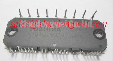
MIG10J503H is identified here as a Toshiba Intelligent Power Module. The supplied product information does not state a numerical voltage class or current value, so those limits must be taken from the original Toshiba documentation applicable to the exact production version before a replacement is approved for an electric forklift or warehouse vehicle inverter.
Altitude and terrestrial radiation deserve careful treatment when an inverter is operated above approximately 2000 m. Neutron-induced single-event effects, including possible single-event burnout in high-voltage semiconductor structures, are system reliability subjects rather than published MIG10J503H ratings. No FIT value, SEB probability, or altitude derating factor should be assigned without a qualified device reliability source and a defined operating profile. A practical design consideration is to evaluate the actual DC-link voltage, switching overshoot, ambient pressure, cooling performance, and duty cycle together instead of applying a generic altitude multiplier.
For the copper power path, keep the positive bus, negative bus, and switching return physically compact and arranged to minimize parasitic loop inductance. The purpose is to suppress turn-off voltage overshoot and to keep the measured collector-emitter stress within the verified device boundary during the complete switching event. The final clearance and creepage arrangement must be determined from the working voltage, pollution environment, insulation system, material group, and applicable equipment standard. A layout that appears adequate on a clean laboratory bench may require a different spacing strategy in a dusty warehouse or a condensation-prone cold store.
Gate-drive routing should use a controlled return path that does not share high-current commutation copper. Common-mode ground bounce can shift the apparent gate-emitter voltage and create false turn-on or incomplete turn-off. Where gate and emitter connections are accessible, designers should verify the gate waveform with a suitable differential probe, paying attention to the reference connection and probe loop area. Otherwise, use the documented control and diagnostic terminals without assuming access to the internal gate circuit. A negative turn-off bias must not be assumed for this model unless it is stated in the applicable Toshiba gate-drive information; control voltage, internal gate-drive arrangements, and dead-time requirements must be checked against that documentation.
Where a field replacement is being evaluated, compare connector position, terminal function, mechanical envelope, insulation spacing, control logic, protection feedback, and thermal interface before energizing the drive. The reference link SKIIP37AC12T4V1 describes a separate device, not an established replacement; electrical and mechanical equivalence must be demonstrated by the system engineer rather than inferred from package appearance.
Benchtop Waveform Tuning and Fast-Switch Overvoltage Trip Prevention
Capture the DC-link waveform at the power module during motor deceleration and compare it with the controller’s overvoltage trip signal before changing braking parameters. The timing relationship reveals whether the braking path is responding early enough, whether the measurement point is remote from the module, and whether wiring inductance is adding a local voltage peak that the controller does not see.
In an electric material-handling vehicle, regenerative energy from the traction motor can raise the DC link when the battery or front-end converter cannot absorb the returned energy. If a braking chopper and ballast resistor are used, they must be selected from the complete kinetic-energy profile, allowable duty cycle, DC-link operating range, resistor pulse capability, cooling conditions, and the protection response of the drive. The available product information does not specify an internal braking IGBT or a ballast-resistor rating for MIG10J503H, so those functions should not be attributed to the module without the relevant circuit documentation.
An engineering calculation may estimate the required braking energy from the motor speed, reflected inertia, gradient, payload, and deceleration command, but the result is only meaningful after battery absorption and mechanical brake contribution have been included. The resistor must tolerate the resulting pulse energy and repetition pattern, while its thermal behavior must be evaluated at the enclosure level. A resistor selected only from continuous wattage can be unsuitable when short regenerative events repeat frequently during warehouse traffic.
Fast semiconductor fuse coordination requires comparison of the fuse clearing integral with the prospective fault current and the module’s published short-circuit, surge, and thermal limits. The fuse must interrupt quickly enough to limit destructive energy, but its actual clearing behavior depends on fuse construction, current rise rate, circuit inductance, bus capacitance, and fault location. A fuse I²t value should therefore be checked against the complete protection network rather than treated as an isolated guarantee of module survival.
For short-circuit protection, a desaturation or collector-emitter monitoring circuit can support a controlled soft turn-off, provided the gate driver, blanking interval, fault latch, and isolation path are correctly matched. In an IPM, these functions may be internal; their presence and behavior must be confirmed from the module documentation. The safe short-circuit operating area and response timing must come from the device documentation and the gate-driver design. Do not apply a generic soft-shutdown voltage or timing value to this model without verifying the documented drive arrangement and measured collector-emitter transient.
During bench tuning, begin with a current-limited low-energy test and observe the accessible control or gate-emitter signal, collector-emitter voltage, DC-link voltage, and fault feedback on the same time base. A ringing gate signal, where it can be measured, may indicate common-mode coupling, insufficient damping, an unsuitable probe reference, or an unstable driver layout. The corrective action should follow the measured waveform, with the switching loop and gate loop treated as separate physical circuits.
MIG10J503H Operational Boundaries and Thermal Feedback Limits
Check the temperature difference between the module case, heatsink, and nearby bus hardware while the inverter delivers a stable traction current, then compare the readings across phases under the same mechanical load. Unequal temperatures can arise from contact resistance, airflow imbalance, unequal electrical impedance, sensor placement, or phase loading, so the measurement pattern is more useful than a single temperature value.
A positive temperature coefficient of on-state voltage can support static current sharing between parallel power semiconductor paths, because a warmer path may develop a higher conduction voltage and naturally discourage additional current. The coefficient depends on device characteristics and operating current and must not be assumed across the full operating range. This is a design consideration, not a guaranteed parallel-sharing specification for MIG10J503H. Dynamic sharing during turn-on and turn-off is governed by gate-loop inductance, driver timing, device parameter spread, commutation layout, and load current. These conditions must be verified on the assembled inverter.
When multiple power paths are used, keep the gate-drive wiring symmetrical and provide comparable power-loop impedance for each path. Avoid allowing one branch to use a shorter gate return while another branch shares a noisy emitter or control reference. For an IPM with internal gate drives, follow the documented control-interface routing and parallel-operation requirements rather than assuming that the internal gate wiring is accessible. The gate driver should be checked for common-mode displacement during the fastest voltage transition, since a ground bounce event can create an apparent gate command that does not exist at the controller output.
Thermal coupling through the heatsink can also influence current balance. A module installed with uneven contact pressure or inconsistent thermal interface coverage may show phase-to-phase temperature differences even when the electrical waveform appears similar. The applicable mechanical installation method should follow the original Toshiba mechanical guidance and the heatsink manufacturer’s requirements. Generic torque values should not be presented as a MIG10J503H factory specification.
For industrial forklift traction, inspect the heatsink fins, fan path, enclosure intake, and temperature-sensor attachment during scheduled service. Dust accumulation increases thermal resistance, while cold-to-warm transitions can produce condensation around terminals and control connectors. The system integrator should verify sealing, drainage, heater strategy, and insulation condition for the actual vehicle enclosure rather than assuming that the IPM alone establishes environmental protection.
⚠️ Maintenance Note: Isolate the DC link and verify discharge before touching the module, then periodically monitor terminal temperature rise and confirm that the cooling airflow remains unobstructed.
Gate-drive protection should be assessed together with the power stage. Miller-induced turn-on, an inadequate gate clamp, or a noisy isolated supply can increase switching loss without immediately producing an obvious controller fault. The engineering guide Precision Gate Drive Design provides relevant background for reviewing gate-loop impedance, common-mode behavior, and protection coordination without replacing the Toshiba-specific electrical limits.
Field Diagnostics and Commissioning for Thermal Time Constants
Record case temperature, heatsink temperature, phase current, switching frequency, and pulse duration during the exact overload event that causes the drive to trip. Compare the thermal response with a known-good operating trace, because a delayed temperature rise may reflect heatsink thermal mass while a rapid case increase can point to contact resistance, abnormal conduction loss, or insufficient cooling.
The junction temperature cannot be obtained reliably from a case thermometer alone during a short overload. A transient thermal model normally represents the junction-to-case and case-to-heatsink paths with several time constants, allowing the engineer to estimate how a pulse contributes to junction heating before the case temperature has visibly changed. That estimate is valid only when the thermal impedance data, mounting condition, interface material, and pulse waveform correspond to the actual assembly.
For MIG10J503H, no numerical transient thermal impedance curve, junction-temperature limit, or overload duration is provided in the supplied product facts. Manufacturer limits must therefore be taken from the applicable Toshiba documentation; controlled thermal testing may validate an assembly model but does not establish the manufacturer's maximum junction-temperature rating. It would be unsafe to calculate a peak junction margin from a generic IPM curve or from the package label alone.
Commissioning should combine electrical and thermal evidence. Use the oscilloscope to inspect collector-emitter overshoot and accessible gate or control signals, while the thermal system records the case response over repeated acceleration and braking cycles. A recurring trip after several cycles may reflect accumulated heatsink energy, restricted airflow, increased conduction loss, or a protection threshold reached by the control system. The symptom does not establish one cause without correlating the traces.
Inspect the mounting plane for contamination, distortion, and uneven interface coverage, then check that the heatsink remains mechanically stable after thermal cycling. Verify phase-terminal tightness according to the original assembly instruction and inspect for discoloration, localized heating, or insulation tracking. Creepage and clearance must remain free of conductive dust, moisture films, and damaged insulating barriers, particularly where the traction enclosure experiences frequent temperature changes.
Where an overload involves a motor reversal or rapid stop, review the energy path as well as the semiconductor temperature. A high DC-link excursion can trigger protection before the module reaches its apparent thermal limit, while repeated current pulses can raise junction temperature without producing a large bus-voltage change. The final commissioning decision should be based on measured voltage, current, control, protection, and thermal margins under the intended duty cycle.
For technical purchasing, the applicable Toshiba documentation should be matched to the exact MIG10J503H marking, package arrangement, control interface, and equipment revision. This prevents a mechanically similar IPM from being assessed with the wrong voltage, current, thermal, or protection assumptions. The product reference is available at MIG10J503H.