Content last revised on September 24, 2026
Full-Screen Primary-Color Screening: Stuck Subpixels and Background Uniformity Audit
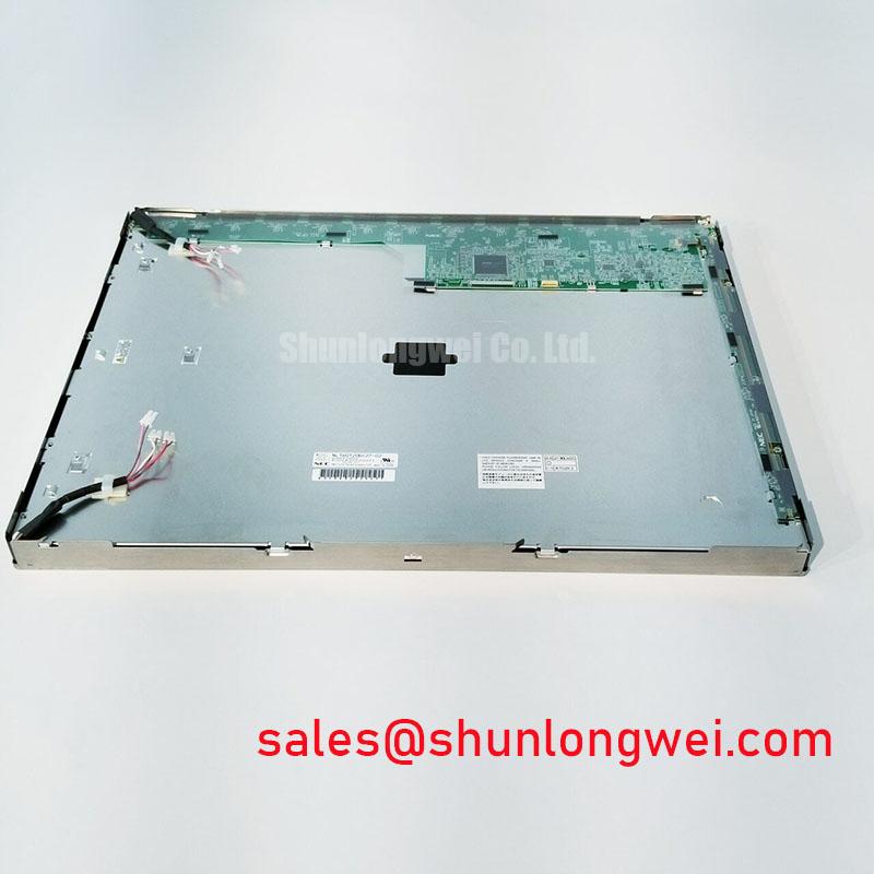
Start incoming inspection by checking the NEC NL160120BC27-19E module against the original equipment documentation, then examine the bezel, glass surface, connector area, and flexible cable for impact marks, contamination, or mechanical displacement before applying power.
Perform the first optical check with the panel disconnected from the equipment harness and protected against electrostatic discharge. After installation on a controlled test fixture, display full-screen black, white, red, green, and blue images in sequence. Use the same image scaling and signal path for each color so that a defective source signal is not confused with a panel defect. Record pixels that remain dark, bright, or fixed at one color, and mark their screen position rather than relying on memory during later comparison.
The NL160120BC27-19E is identified in the supplied factory specification context as an industrial grade LCD/HMI panel manufactured by NEC. Its package classification is a TFT LCD display module, and its specification status is listed as Official Factory Spec Verified. The supplied data does not confirm display resolution, active area, viewing angle, logic voltage, interface mapping, backlight type, or operating temperature limits. Those values should be taken from the original panel documentation or the equipment service manual before electrical integration.
For a high voltage substation protection or SCADA dispatch console, the practical replacement question is not limited to physical fit. The replacement panel must also match the host controller timing, connector orientation, power sequence, backlight drive method, mounting clearances, and optical requirements of the original display assembly. The following inspection method keeps those decisions tied to measurable evidence.
Full-screen black is useful for identifying light leakage, edge illumination differences, and bright stuck subpixels. Full-screen white exposes darker areas, contamination, and uneven illumination. The primary colors separate individual subpixel behavior more effectively than a mixed desktop image. A defect that appears in only one color channel may require comparison with a known-good cable and controller before the panel itself is classified as faulty.
A 45-degree flashlight inspection in a darkened test area can help separate a surface or backlight issue from a line defect associated with the driver region. A dark shadow that changes with the angle of the light may be related to surface contamination, mechanical pressure, or illumination nonuniformity. A fixed vertical or horizontal line that remains in the same location across test images requires signal path inspection and careful observation of the bonded driver region. This method is an engineering screening procedure, not a substitute for the manufacturer’s pixel acceptance criteria.
Do not assume that the NL160120BC27-19E uses a particular TTL or LVDS implementation. The supplied factory context does not confirm the interface standard, connector pinout, data mapping, clock frequency, or timing limits. The system integrator should verify the original panel documentation before applying a transmitter signal. Where a serial differential interface is present, inspect clock stability, data hold behavior, and eye quality across the actual industrial temperature range. Where a parallel interface is used, verify signal order and logic thresholds from the host equipment documentation.
Cold temperature testing deserves its own observation period. A display that starts correctly at room temperature may show delayed illumination, incomplete image formation, or transient artifacts after a cold soak. Log the time from power application to a stable image and compare it with the original service acceptance record. If the host controller has a fixed watchdog interval, the integrator should evaluate whether the panel’s actual startup behavior is compatible with that timeout rather than adding an assumed delay.
For an alternative same-family evaluation, engineers can review NL160120BC27-14 as a separate model reference. It should be treated as an independent compatibility candidate, with resolution, connector, electrical timing, mounting dimensions, and optical performance checked against the original assembly before any substitution decision.
CCFL High-Voltage Resonant Inverter Ignition Debugging
The supplied information for the NL160120BC27-19E does not identify its backlight technology or confirm a dual-channel CCFL inverter interface. Do not connect a CCFL inverter or LED driver based only on the panel model number. First inspect the original equipment wiring, connector keying, backlight control signals, and service documentation. The system integrator should verify whether the replacement panel requires a dedicated inverter, an integrated driver, or another arrangement documented by the original equipment manufacturer.
If the host system uses a CCFL assembly, ignition troubleshooting must be performed with equipment rated for the high-voltage waveform and with the appropriate guarding in place. An ignition failure may involve the inverter, lamp wiring, connector insulation, grounding arrangement, control enable signal, or the lamp assembly itself. A single no-light symptom does not identify one defective part. Compare the enable and dimming signals with a known-good channel, inspect the harness for evidence of tracking, and evaluate the inverter output only with a suitable high-voltage probe and measurement procedure.
Acoustic noise during startup should be investigated by correlating the sound with the inverter operating state, mechanical mounting, and supply behavior. Loose brackets, transformer vibration, uneven enclosure pressure, and an unsuitable drive condition can produce similar symptoms. The panel documentation and original inverter specification should define the permitted operating relationship; unsupported assumptions about striking voltage, lamp current, or operating frequency should not be presented as specifications of this NEC module.
If the original assembly uses LED backlighting, the service procedure changes. Verify the LED current control method, enable polarity, dimming interface, fault response, and thermal conditions from the equipment documentation. Do not infer a particular PWM dimming ratio or brightness half life for this model because those values are not included in the supplied official parameter set. A constant-current driver may be appropriate for one assembly and unsuitable for another, depending on the actual LED string arrangement.
Signal integrity around the display harness also needs a system-level check. If the interface uses differential pairs, maintain the original pair assignment and reference structure, minimize unnecessary discontinuities, and inspect the connector transition rather than focusing only on the cable length. A measured impedance value or skew limit should come from the applicable interface specification and the controller design. The display model information provided here does not establish a universal 100-ohm requirement for this panel.
For a wider equipment architecture review, the related NL8048AC19-13KD page may be used as a separate display solution reference. It does not establish electrical compatibility with the NL160120BC27-19E, so the power and signal interfaces must remain verified independently.
Controlled Differential-Impedance Flex Routing to Suppress High-Frequency Jitter
Flexible cable handling is a frequent source of intermittent display faults during maintenance. Before insertion, confirm that the contacts are clean and that the cable is aligned with the connector guide. The flex should enter without lateral force, twisting, or a sharp crease at the connector exit. Its bend path must be determined by the original mechanical assembly and the cable supplier’s limits, because the supplied panel data does not state a permitted bend radius or flex cycle life.
After locking the connector, apply only the mechanical retention method specified by the connector design. A cable that appears electrically functional on a static bench can still open intermittently when the enclosure is assembled, the display frame is tightened, or the equipment experiences vibration. Perform a powered flex and harness movement check only within a controlled service fixture, while monitoring the image for brief line loss, split-image behavior, clock interruption, or color changes. These symptoms require comparison against the known-good signal path before assigning the fault to the panel.
The logic supply voltage is not confirmed in the supplied official parameters. Do not assume a 3.3 V or 5 V supply. The system integrator should verify the required voltage, polarity, current demand, and power sequencing from the original panel documentation. Measure the supply at the panel connector during startup and observe whether the host controller enables data before the display reaches its required operating state. If the controller has reset supervision, compare the actual rise and settling behavior with the controller manufacturer’s requirements.
Data mapping must also be verified rather than inferred from a similar NEC model. JEIDA and VESA arrangements can place color bits differently, and an incorrect mapping may produce abnormal colors or image segmentation without causing permanent panel damage. Confirm the mapping, clock polarity, lane assignment, and connector pinout from the original technical documentation. An oscilloscope comparison against a known-good unit is appropriate when the image shows intermittent artifacts or instability that cannot be reproduced with a static continuity test.
For high voltage substation protection and SCADA dispatch console evaluation, mechanical stress should be assessed with the panel installed in its actual bezel or bracket. The frame should support the module without pressing directly on the active area. Vibration and shock testing should follow the equipment qualification method and the panel manufacturer’s limits. Do not assign a generic industrial vibration rating to this model without a documented source. If the console is installed in a cabinet with fans, relays, or contactors, inspect whether cable routing brings the display harness close to switching conductors and revise the route only after confirming clearance and grounding requirements.
Long static screen operation should be evaluated with the real HMI content. Fixed alarm bars, grid lines, station identifiers, and bright status icons may produce image retention depending on the panel technology and operating conditions. Use the original maintenance procedure for screen refresh, brightness control, and rest periods where such procedures are specified. The supplied factory data does not confirm an image retention limit or guaranteed operating life, so those conditions must not be represented as a model-specific guarantee.
Surface Anti-Glare and Anti-Reflective Behavior for High Ambient Readability
Inspect the front surface under both diffuse room light and a directional lamp before powering the display. Look for scratches, pressure marks, uneven cleaning residue, and reflections from the cabinet window. A surface that appears acceptable when dark may reveal haze or contamination on a white screen. Use a clean, approved material and the equipment maintenance procedure when removing residue; excessive pressure can create a temporary optical mark or impose stress on the panel assembly.
The supplied specification context does not confirm whether the front surface of the NL160120BC27-19E has an anti-glare coating, an anti-reflective treatment, a bonded cover, or another optical construction. Confirm the original mechanical drawing and service instructions before selecting a replacement window or applying a cleaning agent. An external cover can change contrast, reflection, touch response, and thermal behavior even when the panel connector is electrically compatible.
Viewing angle should be evaluated from the operator’s actual position rather than accepted from a generic panel category. Display a grayscale ramp, colored alarm screen, and fine text while checking horizontal and vertical movement around the intended viewing direction. If grayscale inversion, color shift, or reduced contrast appears, record the angle and cabinet geometry. The available official context does not provide a numerical viewing cone or confirm TN, IPS, or MVA construction, so those characteristics require direct documentation or measurement.
Ambient light assessment should include the cabinet window, overhead fixtures, emergency lighting, and reflections from nearby instrument panels. Adjusting screen brightness may improve readability but can also affect thermal conditions and long-term image stability. The appropriate setting is system-determined and should be verified against the equipment operator’s visibility requirements. A display that is readable on a workbench may remain unsuitable when installed behind a reflective protective window.
Bench Tip: Disconnect power before inserting or removing the flex cable, use ESD protection, and confirm that the cable is fully square in the connector before locking it.
When the display is part of a harsh industrial HMI assessment, the practical inspection and integration principles in Industrial Display and HMI Solutions can provide additional context for enclosure, optical, and service access evaluation. The final compatibility decision remains dependent on the original equipment records and measured behavior of the installed system.
| Parameter | Verified information |
|---|---|
| Model | NL160120BC27-19E |
| Manufacturer | NEC |
| Product category | Industrial grade LCD/HMI panel |
| Package or enclosure | TFT LCD display module |
| Specification status | Official Factory Spec Verified |
| Unconfirmed integration data | Resolution, dimensions, interface, logic voltage, backlight type, timing, viewing angle, and temperature limits require verification from the original panel documentation |