
Content last revised on September 10, 2026
Product Identification and Service Assessment
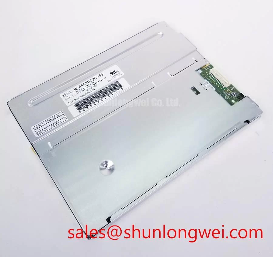
Begin service assessment by confirming that the installed panel label reads NL6448BC20-21, then isolate power before reseating the display connector or examining the enclosure for bezel distortion, cable strain, moisture traces, or uneven backlight appearance.
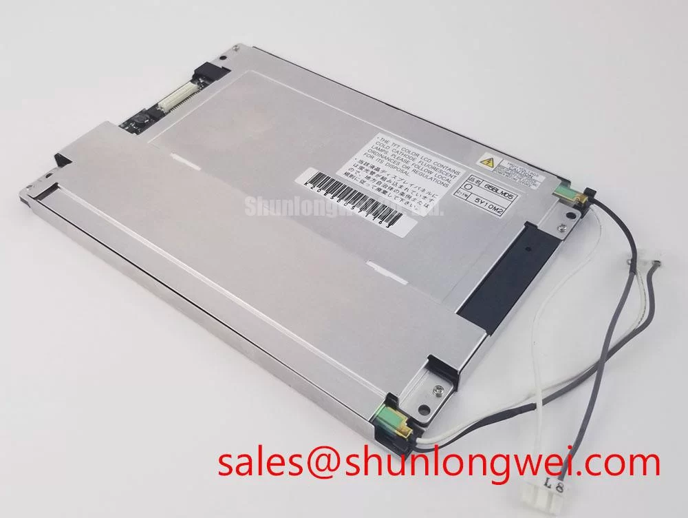
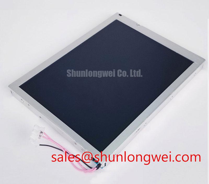
The NEC NL6448BC20-21 is identified as an Industrial Grade LCD/HMI Panel supplied as a TFT-LCD Display Module. Its electrical input requirements, interface assignment, native resolution, luminance, viewing direction, backlight construction, mechanical dimensions, and environmental limits must be confirmed against the original equipment documentation before a replacement panel is powered in a live machine.
| Item | Product Identification |
|---|---|
| Model | NL6448BC20-21 |
| Manufacturer | NEC |
| Product category | Industrial Grade LCD/HMI Panel |
| Module type | TFT-LCD Display Module |
| Specification status | Requires confirmation against original factory documentation |
Contrast, Temperature, and Optical Performance Checks
When a machine display looks washed out in bright daylight, first separate an optical issue from a signal issue. Inspect the panel with the same image source under controlled indoor light, then compare it under the actual enclosure window and operating illumination. A contrast change that follows ambient light often points toward surface reflections, contamination on a protective window, enclosure glare, or a dimmed illumination path rather than an immediate failure in the pixel drive path.
Liquid crystal optical behavior changes with temperature. The liquid crystal layer controls light transmission through electrically driven orientation, and its response can visibly shift as ambient temperature changes. This is a Design Consideration, not an NEC rating for this specific model. Engineers should observe whether grayscale transitions, dark tones, and off axis readability remain consistent after the panel and enclosure have reached their actual operating temperature.
TN, IPS, and MVA technologies can differ significantly in viewing behavior and grayscale inversion characteristics, but the display mode of NL6448BC20-21 should not be assumed without the original NEC documentation. Do not use a broad viewing angle claim from another panel family as a compatibility decision. Verify the original panel drawing, viewing direction, optical treatment, and acceptance criteria used by the host equipment manufacturer.
For a panel mounted behind a cab window, anti glare performance must be assessed as an enclosure level result. Surface haze, cover lens angle, window cleanliness, sun direction, and reflected dashboard surfaces can all affect perceived contrast. If a protective front lens has been added during repair, compare the image before and after installation. A clear lens can increase reflections even when the LCD itself is functioning correctly.
During black screen troubleshooting, check whether a faint image remains visible under carefully controlled illumination. A faint but structured image can indicate that image data is present while the illumination chain requires further inspection. A completely blank result does not establish a single cause. Confirm panel supply sequencing, connector seating, source board output, and the original signal path with appropriate test equipment before attributing the condition to the LCD module.
For a same class display comparison during an engineering review, the NL10276BC16-06 can be examined as a separate NEC display option. Such a comparison should begin with confirmed mechanical drawing data, interface timing, resolution, connector location, and original equipment software support. Similar product naming or a similar screen class is not evidence of direct interchangeability.
Backlight Output and Illumination Reliability Checks
Before diagnosing reduced brightness as a panel defect, verify the full illumination chain. Check the host power source, backlight enable behavior, brightness control command, cable retention, and display connector condition. If the original equipment uses a separate illumination driver or control board, the system integrator should verify the required supply voltage and control requirements from the original panel documentation. These values are not confirmed by the available factory identification data for NL6448BC20-21.
L70 and B50 are useful reliability terms only when supported by a stated test method, operating condition, and manufacturer data. No numerical backlight lifetime, lumen maintenance interval, or LED half life claim should be assigned to this NEC model without its matching factory specification. For maintenance planning, record the panel operating hours from the machine controller where available, inspect for nonuniform illumination, and compare brightness behavior against a known good signal path.
Localized heating near narrow display edges can influence the perceived uniformity of an LCD assembly. Design Consideration: the panel mounting arrangement should allow the host chassis to manage its own thermal conditions without applying uneven pressure to the display perimeter. The system engineer should validate enclosure temperature distribution during realistic duty cycles, especially where the panel is installed near power electronics, radios, or heated operator controls.
Cold conditions can slow liquid crystal movement and make moving graphics appear to lag. This is a general display behavior and is not a confirmed response time specification for NL6448BC20-21. If a machine powers up in low ambient temperature, observe a static test image first, then test page changes, moving icons, and alarm transitions after the display assembly has stabilized. A slow visual transition can be related to temperature, source timing, interface integrity, or the application controller; the evidence should be collected before changing hardware.
Heater strips, if used in an equipment enclosure, are system level hardware rather than a documented feature of this LCD module. Their control logic, placement, temperature sensing, and power budget must be established by the machine design. Avoid placing unverified heating elements against the panel assembly. The correct integration approach is to validate the enclosure thermal profile and confirm that all conditions remain within the original panel documentation.
A display investigation can also include adjacent hardware where appropriate. The NL10276BC30-24D is a separate display module that may be relevant to a broader inventory or architecture review, but it must be evaluated independently against the installed panel’s electrical, mechanical, and optical requirements.
Field Alert: Disconnect system power and allow stored energy in the host equipment to discharge before inserting or removing a display connector, because signal pins should never be treated as safe to hot plug without the original system procedure.
Chassis Fastening and Optical Mura Control
Mechanical installation should begin with a clean inspection of the receiving bezel, mounting bosses, cable route, and support surfaces. Check for burrs, trapped debris, warped brackets, displaced gasket material, and points where the chassis can bear directly on an active display area. Uneven mechanical loading can create local changes in brightness or dark field appearance that are often described as mura. The visible pattern may change when the screws are loosened, the bezel is supported, or the temperature changes.
The fastener torque range sometimes used in general display assembly practice must not be treated as an official NEC requirement for NL6448BC20-21 unless it appears in the matching mechanical drawing. Design Consideration: use the original equipment fastening procedure, tighten progressively in a cross pattern where the enclosure design calls for it, and inspect the displayed image after final assembly. The required torque depends on the bracket design, screw engagement, washer stack, gasket compression, and mechanical support provided by the equipment chassis.
A panel can remain electrically functional while showing installation induced optical defects. Inspect for edge brightening, dark corners, pressure marks, color variation, or a pattern that changes when the bezel is touched. These observations do not prove a single root cause. They provide a practical basis for checking mounting force, chassis flatness, cover lens fit, and whether an external cable is pulling on the module connector.
For vibration exposed equipment, cable retention deserves the same attention as the front bezel. Route the display cable so that normal machine movement does not place continuous tension on the connector. Confirm that locking features are fully engaged according to the original host assembly. Repeated bending close to a connector can cause intermittent symptoms that resemble panel faults, including flicker, lines, unstable color, or loss of image during vibration.
Optical bonding, front glass, sealing layers, and environmental protection methods should not be presumed for this model. If the host display uses a bonded cover assembly or an external sealing solution, treat it as part of the equipment assembly. During replacement assessment, confirm whether the original panel was installed directly behind a protective window, within a gasketed bezel, or with an additional optical layer. A replacement decision should preserve the mechanical stack that the equipment was designed to use.
Cold-Start Display Response and Machine Power-Up Checks
Cold start evaluation should use the actual machine startup sequence rather than a brief bench observation. Begin by confirming that the host controller starts correctly, then watch for panel initialization behavior, stable image formation, repeated blanking, color instability, and delayed updates. Capture the power and signal sequence with suitable instruments when a repeatable fault is present. A white screen, intermittent image, or delayed picture can arise from several locations in the chain, including the source controller, timing relationship, connector path, display supply, or the LCD module itself.
Gray to gray response can become slower as liquid crystal viscosity increases at lower temperature. This is a Design Consideration, and the supported temperature range for NL6448BC20-21 must be verified from the original NEC document rather than inferred from an industrial application. Where low temperature operation is expected, system engineers should test the actual interface content after cold soak, including low contrast text, cursor movement, alarm colors, and rapid page changes.
Do not assume a TTL or LVDS interface for this model without confirming the factory documentation. The system integrator should verify the panel interface type, connector pinout, clock requirements, data mapping, supply sequence, and signal timing from the original panel documentation. If an oscilloscope comparison is available, compare the installed signal path with a known good path and look for timing instability, excessive noise, missing enable behavior, or changes linked to cable movement.
Power sequencing is especially important when a panel is replaced after a control board repair. The host system should apply and remove panel power, logic signals, and any illumination control according to the original equipment requirements. The correct order and delay values are system determined unless published in the panel datasheet. Avoid using assumed timing values from unrelated LCD modules, since a display that powers on during a bench check may still show intermittent startup behavior in the complete machine.
For long term industrial HMI service, static screen retention should be assessed through the actual user interface. Where a machine remains on one page for extended periods, operators and service teams can document whether a temporary image trace clears after normal content changes. This observation should be distinguished from a permanent optical defect, contamination, or a source image problem. The equipment designer determines screen management policies, refresh behavior, and any standby routines.
Maintenance teams evaluating an NEC LCD for industrial HMI, monitoring terminals, or a heavy equipment telematics display can use The Ultimate Guide to Industrial TFT LCD Technology as a general reference for panel technology, integration checks, and common display selection considerations. Final replacement approval should remain tied to the confirmed requirements of the original NL6448BC20-21 installation.