


Content last revised on September 24, 2026
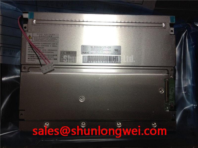
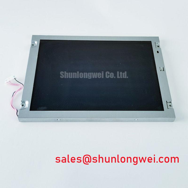
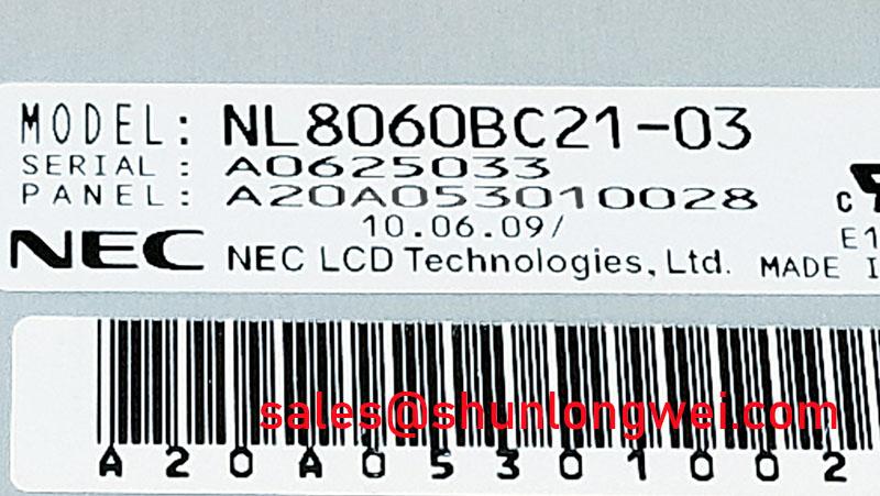
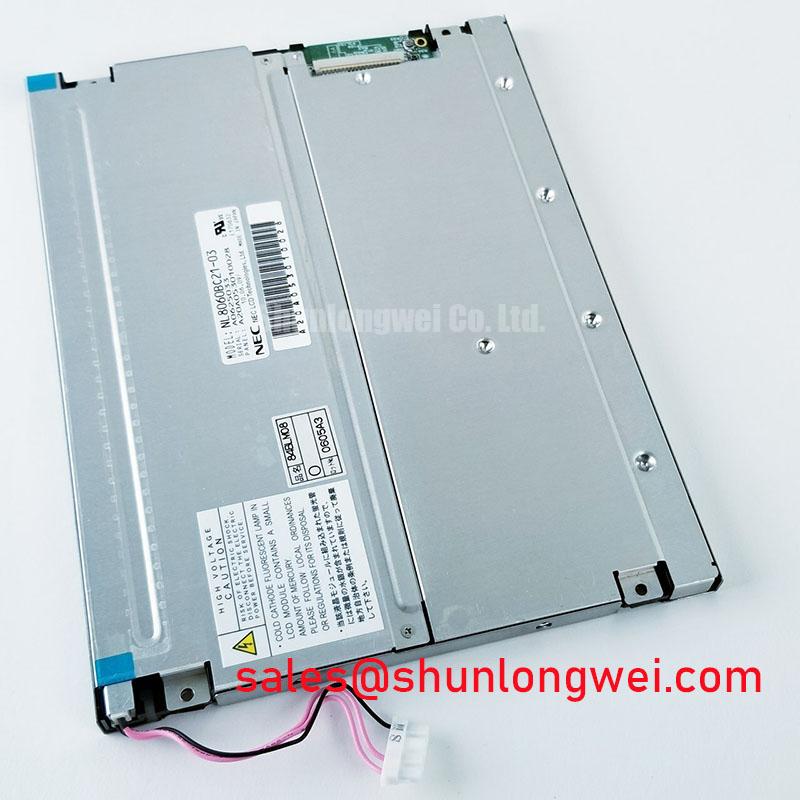
NEC NL8060BC21-03 TFT-LCD Display Module for Industrial HMI
Before fitting the replacement, isolate the display assembly, inspect the bezel and connector area under controlled lighting, and compare the panel marking with the equipment service record. The NEC NL8060BC21-03 is identified as an Industrial Grade LCD/HMI Panel and a TFT-LCD Display Module. Its status is listed as Official Factory Spec Verified. Because the available factory information does not confirm the interface mapping, logic supply, backlight architecture, optical bonding method, or mechanical envelope, the system integrator should verify those items against the original panel documentation before installation.
This display module can be evaluated for industrial operator interfaces, monitoring equipment, and specialist consoles such as harsh marine radar and navigation bridge terminals. That application remains subject to the enclosure design, salt mist protection, optical requirements, connector compatibility, and the original equipment manufacturer’s electrical documentation.
| Item | Verified information |
|---|---|
| Manufacturer | NEC |
| Model | NL8060BC21-03 |
| Product category | Industrial Grade LCD/HMI Panel |
| Construction category | TFT-LCD Display Module |
| Specification status | Official Factory Spec Verified |
Preventing Localized Light Guide Plate Compression Warp on Dark Screen Fields
During installation, place the module on a clean, level work surface and check that the chassis bezel contacts the display assembly evenly. Uneven frame pressure can create visible dark-field non-uniformity, local optical shading, or pressure-related mura. These symptoms should not be assigned to the panel alone until the mounting frame, gasket position, screw loading, and connector clearance have been inspected.
The outer bezel envelope is a system-level mechanical condition rather than a confirmed factory dimension for this model. Designers should obtain the original mechanical drawing or measure the removed assembly before fabricating a replacement bracket. The frame should support the panel without forcing the glass, flex circuit, or rear housing into a twisted position. Cross-pattern fastening is a useful engineering recommendation because it distributes contact pressure progressively instead of loading one corner before the others.
The supplied installation design should also account for thermal expansion between the display frame and the host enclosure. A marine bridge console may experience enclosure temperature changes, vibration, and airborne salt contamination, but the suitability of this module for that environment depends on the complete enclosure and not on the display module designation alone. The sealing material should remain clear of the visible area and should not press directly on unsupported glass regions.
High-speed display interface routing is another design consideration. If the original system uses a differential video link, preserve the established pair geometry, reference plane, return path, and connector orientation. A target such as 100 Ω differential impedance may be relevant to the host interface design, but it is not presented here as an official electrical specification of the NEC NL8060BC21-03. The integrator should confirm the required interface standard and signal mapping from the equipment documentation before routing a new harness.
For comparison work, the NL10276BC16-06 may be reviewed as a related display reference. It should not be treated as a direct substitute without confirming dimensions, connector location, interface timing, optical characteristics, and the complete host-panel compatibility list.
Micro-Twist Mechanical Stress Fracture Prevention on Glass Substrate Driver Bumps
Glass-supported display assemblies should be handled by the frame and never lifted by the flexible circuit, connector, or exposed edge of the glass. A panel can pass a basic power-on check and still require a more careful inspection if it has been subjected to twisting during removal. Look for repeating vertical or horizontal line defects, intermittent image changes when the harness is moved, and defects that vary as the enclosure pressure changes. These observations may indicate a connection or mechanical stress issue, but they do not establish a single failure cause without comparison testing.
A practical bench procedure is to display primary red, green, and blue fields in sequence, followed by white, black, and mid-level grey images. Observe the panel directly from the intended viewing position, then use a flashlight at approximately forty-five degrees to examine dark areas without pressing the glass. This can help distinguish a general backlight or illumination problem from a line-related display defect. The result should be recorded with the panel flat, supported, and connected to a known-good host signal path.
The flexible cable should follow the original bend path with no sharp fold at the connector exit. The connector lock must be fully engaged, but excessive force should be avoided because a locked connector can still be misaligned. Before applying power, inspect for contamination, shifted contacts, damaged stiffeners, or a cable that is trapped between the bezel and chassis.
Low-temperature operation requires separate consideration. Liquid crystal response can become slower as ambient temperature falls, so a cold display may show visible response-time elongation without having a permanent defect. If the equipment is expected to start in sub-zero conditions, the system designer should verify the panel’s specified operating range from the original NEC documentation and assess the enclosure heater, airflow, condensation control, and startup sequence as a complete system. Do not infer a qualified temperature range from the industrial product category alone.
For long-term maintenance, the cabinet should be checked for condensation paths and salt residue around the bezel. ⚠️ Maintenance Note: Inspect the display gasket, ventilation path, and connector locking condition during scheduled service, especially after repeated thermal cycling or enclosure access.
The engineering guide on Industrial Display & HMI Solutions provides useful system-level context for evaluating sealing, mounting, and harsh-environment display integration. Such guidance should supplement, not replace, the model-specific documentation.
Logic Supply Voltage Sequencing for Driver Protection and Stable Startup
Do not connect the replacement panel to an unverified harness simply because the connector appears mechanically identical. The system integrator should verify the required logic supply voltage from the original panel documentation, including the supply rail, ground arrangement, enable signals, display data format, and backlight control method. The supplied factory information for this product does not confirm whether the host system requires a particular logic voltage, JEIDA mapping, VESA mapping, LVDS arrangement, or another interface configuration.
Power sequencing should be examined with the panel disconnected first. Confirm that the host supply rises cleanly, that enable lines remain in their intended state during startup, and that the display is not exposed to signal activity outside the conditions allowed by the original panel documentation. A white screen, unstable image, or residual image after shutdown can involve supply sequencing, missing enable control, incorrect data mapping, connector contact quality, or host timing. The proper response is to compare the replacement assembly with a known-good signal path rather than assigning the symptom to one component immediately.
If the original design uses differential data, maintain matched routing and a continuous return path. The commonly used 100 Ω differential design target and a tightly controlled pair skew may be appropriate engineering considerations for a specific host interface, but they are not official specifications stated here for the NL8060BC21-03. The system engineer should validate the actual signal quality at the panel connector with suitable probing, checking for overshoot, common-mode disturbance, intermittency, and data-pair imbalance under normal and worst-case operating conditions.
Power-off behavior deserves the same attention as power-on behavior. A controlled shutdown can reduce the possibility of residual charge, incomplete image clearing, or an unintended state in the host display controller. The exact discharge timing must be determined by the system circuit and the original panel requirements. Designers should verify the sequence during repeated cold starts, warm restarts, emergency stops, and controller resets.
Static industrial screens also require operational planning. A fixed status page can expose the display to uneven ageing or persistent image retention depending on the panel technology and drive conditions. The available factory information does not provide a guaranteed retention or burn-in performance figure for this model. Where the application permits, the HMI software team should evaluate screen rotation, controlled dimming, display blanking, and alarm layout changes as system-level measures, then validate the result on the actual assembly.
Managing Backlight Drive Noise and EMI Across the Host Display System
The backlight architecture of the NEC NL8060BC21-03 should be confirmed from the original panel documentation before selecting a driver or modifying the host wiring. The supplied information identifies the unit as a TFT-LCD display module but does not establish whether the installed assembly uses a particular lamp, LED configuration, connector pinout, ignition requirement, or dimming method. A replacement driver should therefore not be selected from connector appearance alone.
When the display is installed near marine radar electronics, navigation processors, radio equipment, or other sensitive circuits, separate the display power path from low-level sensor and communication wiring where the enclosure allows. Minimize current-loop area, provide a deliberate return path, and avoid routing switching backlight conductors alongside high-impedance signal lines. These are design considerations for reducing conducted and radiated interference; the display module itself should not be described as independently compliant with whole-equipment EMC requirements.
Acoustic noise from a driver or enclosure can be investigated by operating the display through its available brightness range while monitoring the suspected source. If the sound changes with dimming or refresh activity, compare the driver, mounting surface, cable routing, and enclosure resonance. This observation can help narrow the inspection but does not prove that a capacitor, transformer, lamp, or switching frequency is the sole cause.
For PWM-controlled systems, the host designer should verify the permitted dimming input, polarity, frequency range, minimum pulse behavior, and startup state from the original driver documentation. Do not assume that a high dimming ratio, LED constant-current drive, or a specific PWM frequency applies to this NEC module without supporting documentation. The panel, driver, cable, and enclosure should be tested together because an acceptable electrical waveform can still produce visible flicker, acoustic noise, or interference after installation.
Moisture protection also belongs to the complete assembly. The display module should be installed within an enclosure whose gasket compression, venting, drainage, and service access have been validated for the intended environment. Optical bonding, full-surface sealing, and salt-fog performance must be confirmed from documented construction data rather than inferred from the TFT-LCD category. Before final closure, inspect the bezel contact line, connector strain relief, cable entry, and any pressure equalization path. Verify the image after the enclosure has been tightened, since mechanical closure can reveal stress or alignment issues that were not present on the bench.