

Content last revised on September 10, 2026
Incoming Benchtop Inspection: COG/TAB Anisotropic Conductive Film (ACF) Integrity
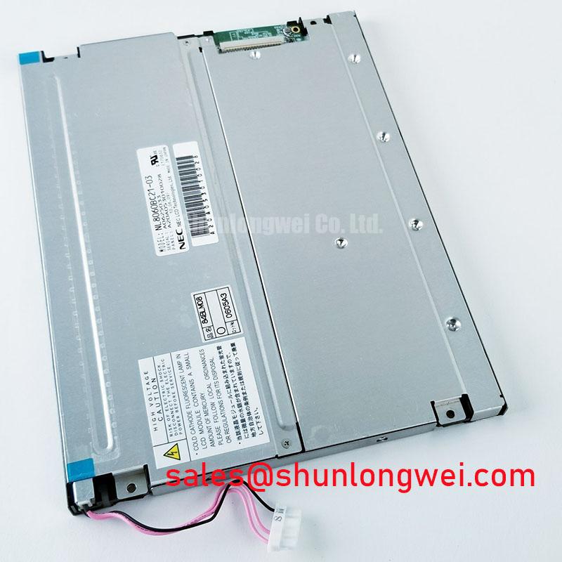
With the unit unpowered, inspect the NL8060BC21-04 viewing area under uniform white, red, green, blue, and black test images before connecting it to host equipment. This is an NEC TFT-LCD display module. The available factory information identifies the model and module type but does not confirm the panel’s electrical supply requirements, interface type, backlight technology, mechanical dimensions, luminance, contrast ratio, operating-temperature range, or response-time data; these items should be verified against the original equipment documentation before an integration decision is made.
| Model | NL8060BC21-04 |
| Manufacturer | NEC |
| Product category | LCD Display Module |
| Module format | TFT-LCD Display Module |
| Specification status | Model and module type identified; detailed specifications require verification |
Start incoming inspection with the panel resting on a clean, grounded, nonabrasive fixture. Check the front polarizer, visible active area, bezel edges, connector region, and any accessible flexible cable for scratches, pressure marks, creases, contamination, incomplete connector latching, or evidence of mechanical loading. A display panel can appear acceptable while unpowered and still reveal line defects, unstable image behavior, or backlight irregularity only after a controlled image test.
Use a known-good host board or qualified panel test fixture whose interface, supply sequence, and connector assignment have been confirmed from the original system documentation. Do not infer the required interface from the module family name. The system integrator should verify the required supply voltage, signal format, pin assignment, timing arrangement, and backlight control method from the original panel documentation.
A practical primary-color examination begins with full-screen red, green, blue, white, and black images. Observe the panel from normal viewing distance and then closer range. Full red, green, and blue patterns make isolated pixel anomalies and column irregularities easier to locate, while white and black patterns help reveal uneven illumination, light leakage, persistent bright points, dark points, or nonuniform areas. Record the test source, panel orientation, ambient lighting condition, and image pattern used so that a later inspection can distinguish a stable condition from a handling-related change.
A flashlight inspection at roughly a 45-degree angle can be useful when the expected image is absent or very dim. With a valid video source present, a faint image visible under oblique illumination may point the investigation toward the illumination path, its control circuitry, or power sequencing. A completely absent image does not establish one single cause. Verify host timing, cable continuity, connector engagement, and the known-good signal path before attributing the result to the display module.
The terms COG, TAB, and ACF describe connection technologies commonly discussed in LCD diagnostics, but their use in the construction of this specific NEC model is not confirmed by the available factory information. For that reason, do not apply pressure to panel edges or attempt to manipulate bonded areas as a test method. Pressure can create a new fault and undermine the value of the inspection result.
💡 Bench Tip: Disconnect power before inserting or removing a display cable, use ESD controls, and confirm that the flex or harness enters its connector squarely before closing any locking feature.
If the original system uses PWM dimming, an engineering recommendation is to observe the dimming waveform and displayed image together during a controlled brightness sweep. A 200 Hz to 1 kHz evaluation window is often useful for checking visible modulation and audible effects in the surrounding assembly, but it is not an official dimming specification for the NL8060BC21-04. The acceptable frequency, duty-cycle behavior, and brightness-control logic are determined by the host electronics and should be verified in the completed equipment.
Industrial EMI Noise Immunity, Chassis Shielding Continuity & Common-Mode Ferrite Chokes
When a panel works on the bench but develops pixel jitter, intermittent horizontal disturbance, flickering regions, or image instability after installation, examine the cable route and chassis return path before assuming the display itself is defective. Industrial equipment can place display harnesses near switched motor wiring, power conversion assemblies, relays, contactors, and variable-frequency motor drives. These conditions can expose an inadequately routed signal path to conducted or radiated interference.
Design Consideration: inspect shield termination as a complete physical path rather than treating the cable braid as a decorative feature. Where the original equipment uses a shielded display cable, preserve its intended chassis-bonding method, strain relief, routing, and connector shell contact. A shield connection interrupted by paint, corrosion, loose hardware, damaged braid, or an unsuitable replacement harness can change the noise behavior of the installed system. Verify continuity using the equipment’s approved grounding scheme and inspect the result in operation.
For installations where the original design includes a common-mode ferrite or filtering element, retain its specified placement and cable orientation. Adding a ferrite without understanding the cable, signal format, grounding arrangement, and source of interference is not a guaranteed correction. Engineers should compare the affected display path with a known-good installation, inspect the waveform at the source and receiver where appropriate, and test changes one at a time. This approach is more reliable than treating any visible horizontal band as proof of one specific EMC mechanism.
The available official information for the NL8060BC21-04 does not provide independent EMC compliance data, immunity limits, shielding requirements, or cable-interface details. The module should therefore not be represented as independently certified to system-level EMC standards. Any equipment-level compliance outcome depends on the enclosure, harnesses, grounding, power architecture, controller, and installation conditions.
Low ambient temperature deserves separate attention during commissioning. Liquid-crystal display behavior can become visibly slower in cold conditions, and apparent image lag may be related to the panel, the host image update path, the illumination system, or the environment. The available data does not establish a sub-zero operating rating for this model. If an AGV or forklift telematics display is being evaluated, technicians should verify the original system’s approved temperature limits and observe startup, text scrolling, color transitions, and touch overlay behavior, if present, at the actual expected ambient condition.
Heater strips, if used by the equipment manufacturer, are system-level assemblies rather than confirmed features of this NEC module. Their control strategy, thermal sensing, power source, and enclosure interaction must be assessed by the equipment designer. Avoid attaching aftermarket heating elements directly to the panel without documented approval, because local mechanical stress and uncontrolled temperature gradients can create issues that are difficult to diagnose later.
For broader troubleshooting context on panel interfaces, optical behavior, and integration variables, consult The Ultimate Guide to Industrial TFT LCD Technology while keeping the original documentation as the authority for this specific model.
Constant Luminance Output Control & L70/B50 LED Half-Life Reliability Verification
Brightness consistency should be assessed as an observed condition of the assembled display rather than assumed from a module description. The official information available for the NL8060BC21-04 confirms a TFT-LCD display module but does not identify the backlight type, its drive current, brightness rating, luminance-control input, expected operational life, L70 value, B50 value, or protection behavior. It is therefore not appropriate to assign an LED lifetime figure, claim constant-luminance capability, or specify a backlight open-circuit or short-circuit response for this model.
During repair evaluation, compare the screen to a known-good panel in the same host equipment when possible. Use identical image content, brightness settings, power source condition, and viewing angle. Uneven brightness, a localized dark area, tint variation, flashing during startup, or a brightness change that follows harness movement may indicate several possible issues. Examine the host backlight driver, connector seating, cable condition, power rail stability, control signal integrity, and panel behavior under repeatable conditions before reaching a diagnosis.
Design Consideration: thermal management should be evaluated at the equipment level. Narrow display edges, mounting rails, protective windows, rear covers, and nearby electronic assemblies can all influence how heat is retained or distributed. If the original design uses conductive rails, thermal pads, or enclosure contact surfaces, preserve the documented stack-up and avoid forcing the panel into a frame that twists the module. The thermal path should support consistent operation without imposing point loads on the display assembly.
Direct sunlight creates a usability problem that cannot be resolved by a contrast-ratio claim unless that claim is confirmed for the particular panel and viewing stack. The factory information supplied here does not specify contrast ratio, anti-glare treatment, sunlight readability, or performance at a stated ambient-light level. For a vehicle-mounted display evaluation, test the installed assembly in representative cab lighting and incident-light conditions. Consider the enclosure window, viewing angle, operator position, surface reflections, brightness-control behavior, and contamination on protective surfaces.
Where a panel replacement is being evaluated for an existing display assembly, the NL10276BC16-06 can be reviewed as a separate candidate for evaluation. It should not be treated as interchangeable solely on a visual comparison or model-family relationship. Confirm active-area fit, mechanical mounting, interface, timing, supply requirements, connector orientation, illumination arrangement, and the original equipment’s acceptance criteria before any substitution is approved.
Service teams should avoid classifying a panel as failed solely because brightness appears reduced. A contaminated front surface, protective cover aging, host-controlled dimming, low input power, a configuration change, cable resistance, or an optical issue elsewhere in the assembly can produce a similar observation. A repeatable test record is more useful than a single visual impression.
High-Humidity Storage Margins (60°C / 90% RH) & Delamination Prevention Protocols
Before placing the NL8060BC21-04 into storage, inspect the shipping condition, protective packaging, connector protection, and panel surface. Keep the module in a clean, dry, ESD-controlled environment and avoid stacking methods that place pressure on the viewing area or cable region. The available official factory information does not provide validated storage limits, humidity limits, thermal-cycle performance, perimeter seal construction, delamination resistance, or a temperature rating from −30°C to +85°C. Those values must not be presented as official ratings for this module.
The 60°C and 90% RH condition is a useful example of a severe environmental exposure that requires documented qualification evidence before it is used as an acceptance requirement. Without a model-specific factory qualification document, it is not possible to state that the panel will tolerate that condition or to predict the result. Moisture exposure, packaging condition, condensation, enclosure leakage, adhesive systems, cable materials, and contaminants can influence the result of an assembled display system.
If a stored panel is moved from a cold area into a warm and humid service environment, allow its condition to stabilize in accordance with the equipment maintenance procedure before power-up. Condensation risk is an assembly-level concern, especially around connectors and controller boards. Visual inspection should include surface moisture, residue, corrosion evidence on accessible contacts, and any change in the appearance of the display layers. Do not use high-pressure air or aggressive cleaning agents near cable interfaces unless they are approved for the equipment.
Cold-start checks should focus on what can be observed and documented: boot image stability, full-screen color rendering, transition behavior, flicker, connector retention, and recovery after normal warm-up. A slow gray transition in cold conditions may be associated with temperature-sensitive display behavior, but the investigation should also include the host graphics controller, supply rails, and communication path. The original system documentation determines whether heating, delayed enable sequencing, or an environmental interlock is required.
Mechanical stress prevention is equally important for mobile equipment displays. In AGV and forklift telematics assemblies, vibration isolation, enclosure rigidity, cable strain relief, and connector retention are system-determined features. Inspect whether the panel is supported evenly, whether the harness can move against sharp edges, and whether closing the enclosure changes the image or applies force near the display perimeter. A panel that performs correctly before final assembly should be retested after the cover, gasket, bracket, and cable-management hardware are installed.
For procurement and repair records, retain the model number, NEC manufacturer identification, host-equipment identifier, observed test patterns, connector condition, and integration findings. This creates a traceable basis for evaluating the NL8060BC21-04 against the actual electrical and mechanical requirements of the equipment without assigning unverified environmental, optical, lifetime, or interface specifications to the module.