Content last revised on October 23, 2026
Thermal Cycling Degradation of Polarizer Adhesives & Sealant Gasket Integrity
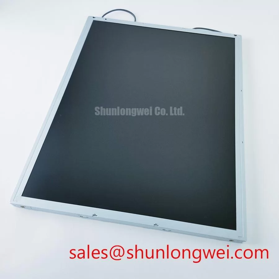
I inspect the unpowered P370IVN04-1 around its viewing perimeter before investigating temperature-dependent image defects, noting edge lifting, uneven frame compression, and any contact between the enclosure and display surface. This separates visible assembly problems from effects that appear only after operation. Polarizer adhesive chemistry, internal sealing materials, and environmental qualification are not established by the model identification alone.
Design Consideration: Lower liquid-crystal temperature generally increases viscosity, which can slow grayscale transitions. When evaluating cold-start behavior, compare the same moving grayscale pattern during stabilization while recording panel-adjacent temperature, image settings, and backlight state. Distinguish persistent image trails from intermittent digital corruption: temperature dependence provides useful evidence, but neither symptom establishes a single cause. Controller compensation should remain within the supported panel configuration rather than being adjusted solely until motion looks sharper.
Design Consideration: Assess perimeter fit through the equipment’s approved environmental test conditions, checking whether enclosure expansion changes bezel clearance or gasket compression. An enclosure gasket and the display cell’s internal seal serve different functions; evidence of compression damage at the former does not establish deterioration of the latter. Avoid transferring a generic industrial temperature range to this AUO panel.
For equipment-level inspection planning, the Industrial Display & HMI Solutions guide provides broader integration context. Keep the product acceptance record specific to the installed module, its mounting arrangement, and the observed image behavior rather than treating environmental discussion as a manufacturer qualification.
Aluminum Heat Spreader Sizing & Thermal Interface Placement along Narrow Display Edges
Map edge temperatures with the display operating in its intended enclosure before changing rail geometry or adding a thermal interface. A narrow metal frame can produce uneven heat paths, so a warm edge should be evaluated alongside adjacent electronics, ventilation, and mounting contact. Identify which surfaces are approved for mechanical contact before treating any exposed frame member as a heat-transfer interface.
Design Consideration: Where the equipment uses an aluminum spreader, its contact area and attachment should follow the measured heat path without applying concentrated pressure to the display stack. Preserve clearance for expansion and cable movement. A thermal pad that bridges an unsupported gap can introduce mechanical loading; selecting thickness and compression therefore belongs to the enclosure design review, not a generic panel replacement procedure.
Design Consideration: Compare brightness uniformity after thermal stabilization using unchanged test images and measurement positions. Edge darkening, color shifts, or brightness drift can have optical, electrical, or mechanical contributors. Do not attribute these observations to PMMA yellowing without material identification and inspection evidence. The overview of optical diffusion explains light redistribution, but does not establish the optical materials inside P370IVN04-1.
For an LED-backlit integration, backlight current regulation and dimming behavior should be assessed against the specified driver interface. Check for visible modulation and camera banding across intended brightness settings without prescribing an unsupported PWM frequency. L70/B50 terminology requires defined test conditions and supporting lifetime data; it cannot establish this module’s service life from an enclosure temperature measurement.
VESA vs. JEIDA Data Mapping Alignment & Even/Odd Channel Signal Integrity
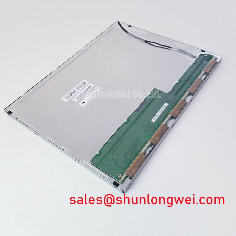
Compare the panel connector drawing with the controller schematic before assigning supply, ground, clock, or data conductors. For P370IVN04-1, replacement approval should include the exact interface definition, logic supply, connector orientation, supported timing, and backlight control arrangement. A matching connector shell does not establish electrical compatibility.
Design Consideration: Where the documented interface is LVDS, align the controller’s VESA or JEIDA mapping with the receiver requirements before changing timing settings. Incorrect bit allocation can alter grayscale or color even when synchronization appears stable. Where the interface divides pixels between channels, verify channel order and pixel assignment using a pattern with distinct alternating columns and recognizable edge markers. Split images can also involve timing or cable faults, so retain the original configuration while isolating each variable.
Compare measured power-up and power-down waveforms with the panel’s specified sequence, including supply stabilization, valid video, and backlight enable. Probe at the receiving end when practical so connector and cable effects remain visible. Rise-time limits and sequencing delays must come from the applicable panel and controller documentation, not from values associated with another display family.
Design Consideration — Pro Tip: Keep each differential pair balanced through routing and connector transitions to protect receiver timing margin, and disconnect power before reseating the display cable.
For a repair bill of materials, record M185XTN01.3 as a separate candidate requiring its own dimensional, optical, and electrical comparison, not as an established replacement for this model. Procurement approval should retain the complete panel designation and revision alongside the verified host configuration; similarity of product category alone is insufficient for substitution.
Grayscale Visibility & Optimal Viewing Direction Alignment
Display a grayscale ramp from the intended operator position before accepting the panel’s installed orientation. Move through the expected viewing positions while holding brightness and source content constant, noting whether dark tones merge, highlight steps disappear, or contrast changes unevenly. This directly tests usability without assigning an unverified TN, IPS, or VA operating mode to P370IVN04-1.
Design Consideration: Grayscale inversion is relevant when evaluating TN displays, but “normally white” and a particular viewing cone are not interchangeable descriptions of every TFT-LCD module. Establish the specified viewing direction before rotating the assembly or changing mounting brackets. If visibility changes after enclosure tightening, compare frame loading and front-window clearance before attempting to compensate through image controls.
Assess reflections with the actual protective window and ambient lighting in place. Surface haze, reflected light, and cover-window spacing can change perceived contrast independently of pixel response. Do not assume an anti-glare etch or a specific surface treatment from appearance alone. AUO Corporation provides manufacturer context for display technologies; model-specific optical acceptance still belongs to the applicable specification.
For potential evaluation in surgical navigation or ultrasound console displays, the system integrator should compare grayscale reproduction, viewing position, image-processing behavior, and equipment qualification requirements. This is a compatibility assessment, not a medical suitability claim. Record the accepted viewing position and front-window arrangement in the equipment service instructions so a later replacement can reproduce the tested optical configuration.