Content last revised on October 11, 2026
PD20DKN16 Thermal-Electrical Optimization: Sinusoidal 10ms Half-Cycle Surge Current: Practical Tuning
With the power assembly disconnected and stored energy discharged, match the terminal markings on the PD20DKN16 to the circuit drawing before taking diode-mode readings. Record both probe polarities with parallel circuit paths isolated; an in-circuit reading can include the snubber, control wiring, or another semiconductor rather than the junction under examination.
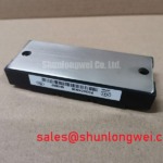
The SanRex (Sansha Electric) PD20DKN16 has a specified voltage rating of 1600 V, a specified current rating of 20 A, and an Isolated Power Module package designation. These are the supplied Official Specification values. The voltage rating is not a terminal-to-base insulation test voltage, and the package designation does not establish an insulation test procedure. For device-specific terminal diagrams and rating conditions, use the manufacturer’s documentation from SanRex Sansha Electric Power Semiconductor Modules.
💡 Bench Tip: With the assembly de-energized, use ESD-controlled handling and compare cold-state readings with a known-good unit at the same temperature and meter settings.
Match the prospective fault-current waveform to the manufacturer’s surge-test conditions before using a sinusoidal 10 ms half-cycle assessment. As a Design Consideration, a non-repetitive surge rating describes a particular event, starting temperature, and recovery condition; it is not a repetitive operating-current allowance. The specified 20 A rating must therefore remain separate from any surge-current assessment.
Before reverse voltage is reapplied after a surge, the evaluation should account for junction heating and the manufacturer’s permitted recovery conditions. A cold case measurement cannot establish the instantaneous junction temperature during the event. Engineers should review the initial thermal state, fault duration, and subsequent blocking stress together rather than approving protection from peak current alone.
A useful fuse-coordination worksheet keeps the semiconductor limits and fuse characteristics in separate columns. The device-specific entries below require the original datasheet; consult it for numerical values rather than extrapolating from the model designation.
| Coordination item | Semiconductor record | Protection record |
|---|---|---|
| Surge-current capability | Non-repetitive rating, waveform, and initial temperature | Prospective fault waveform and interruption time |
| Current-squared-time withstand | Published withstand value and applicable conditions | Fuse total-clearing value at the relevant circuit voltage |
| Post-fault blocking | Permitted recovery and voltage-reapplication conditions | Residual voltage and protection clearing behavior |
Mechanical inspection belongs in this assessment because poor thermal contact changes the starting conditions for a fault. As an Engineering Recommendation, check heatsink flatness, mounting contact, and terminal seating against the module drawing. Apply the specified mounting and terminal torques separately; a generic screw-size torque is not a PD20DKN16 factory requirement.
Field Diagnostics & Commissioning: Surge Energy Dissipation and Clamping Voltage in PD20DKN16 Topologies
Measure the residual transient at the module terminals when assessing AC-input suppression, rather than relying only on the protector’s nominal clamping designation. The relevant surge-immunity reference is IEC 61000-4-5, not “IEEE 61000-4-5”; it concerns equipment testing and does not establish module-level certification.
As a Design Consideration, MOV selection should account for continuous line voltage, temporary overvoltage exposure, surge waveform, residual voltage, and protective disconnection. RC snubber assessment should address ringing and voltage-rise behavior without overlooking resistor heating or capacitor stress. Neither network should be assigned component values from the PD20DKN16 voltage rating alone.
The explanation of transient-voltage-suppression diodes for surge protection provides background on avalanche clamping. It does not establish that a TVS diode is interchangeable with an AC-input MOV. Engineers should evaluate the protection technology against the actual energy source and circuit configuration.
For a potential high-voltage three-phase motor solid-state soft-starter installation, compatibility assessment should establish the required semiconductor arrangement, blocking conditions, control connections, and thermal loading. The linked PD10M440H is a separate comparison reference, not an established equivalent: matching terminal functions, ratings, and mounting geometry must precede any substitution decision.
PD20DKN16 Thermal-Electrical Optimization: High-Frequency Switching Loss Dissipation Practical Tuning
Inspect the commutation-current waveform before attributing excessive case heating to reverse recovery. As a Design Consideration, reverse-recovery peak current and recovery time depend on test conditions, including junction temperature and current-change rate. The supplied voltage and current ratings do not establish fast-switching capability or soft-recovery behavior.
Use synchronized current and voltage measurements to distinguish recovery current from ringing or probe artifacts. Minimize measurement-loop pickup, verify probe ratings, and compare captures under consistent operating conditions. If recovery contributes materially to heating, the system engineer should evaluate commutation conditions and cooling together; changing the snubber alone may not resolve the measured loss.
For incoming inspection, compare forward and reverse diode-mode behavior only across junction paths identified by the terminal diagram. Unexpected readings warrant isolation of external paths and repeat measurement, not an automatic failure diagnosis. Terminal-to-base insulation testing requires its own documented voltage, duration, and connection method.
If an equipment fault also involves its operator display, keep that diagnostic path separate from power-junction testing. The Ultimate Guide to Industrial TFT LCD Technology addresses the display subsystem; display behavior alone cannot establish the electrical condition of the PD20DKN16.