Content last revised on October 21, 2026
Assembly Integrity & Layout Architecture: Implementing Reverse Recovery Charge for PK200FG40
Inspect the commutation path before interpreting a reverse recovery waveform. As a Design Consideration, diode reverse recovery peak current, I_rrm, and recovery time, t_rr, depend on operating conditions as well as device characteristics. Compare measurements at equivalent current, junction temperature, and commutation conditions rather than treating an isolated peak as a module acceptance limit.
During controlled testing, observe device voltage and branch current together using appropriately rated instrumentation. A recovery tail, current peak, or voltage ringing should be evaluated against the switching event and probe arrangement. Minimize unnecessary commutation-loop area to reduce inductive overshoot, with the final layout assessed through system testing. Recovery softness cannot be inferred from the voltage and current ratings alone.
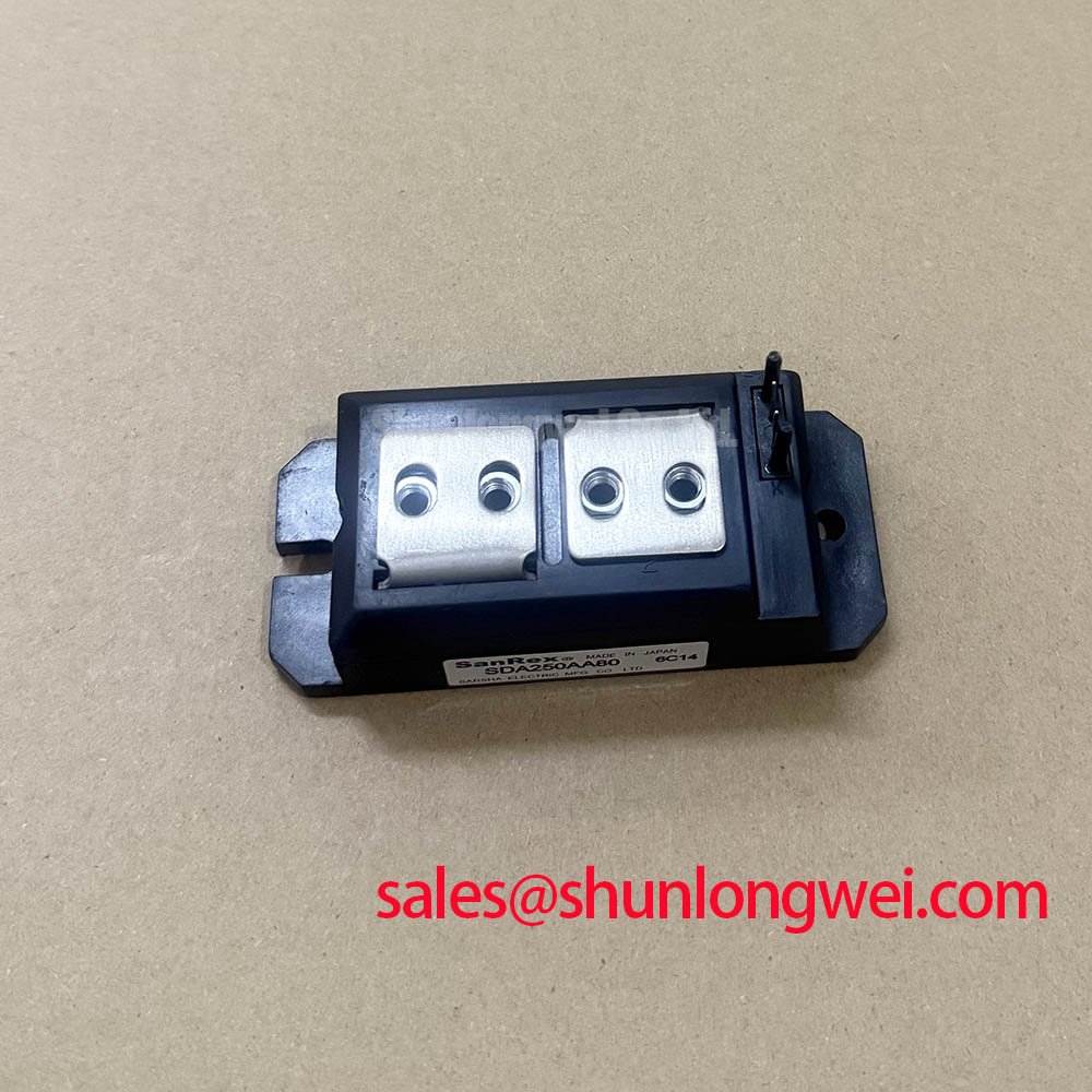
Trace the terminal arrangement against the assembly schematic rather than assuming that similar housings have identical connections. For manufacturer-level product context, consult SanRex Sansha Electric Power Semiconductor Modules. The Shindengen power semiconductor documentation also provides relevant diode and power-device reference material, but does not establish PK200FG40-specific recovery limits.
Where the surrounding rectifier assembly includes other semiconductor stages, assess each stage independently. The PK55GB40 can be considered in that complementary-stage review; its circuit position, terminal arrangement, and protection requirements must match the equipment schematic rather than the similarity of its designation.
Assembly Integrity & Layout Architecture: Evaluating Post-Surge Reverse-Voltage Blocking for PK200FG40
Check the protection record and fuse condition before reapplying reverse voltage after a suspected surge. As an Engineering Recommendation, evaluate nonrepetitive surge current, I_TSM, together with its specified waveform, initial junction temperature, and subsequent voltage conditions. A sinusoidal half-cycle duration of 10 ms is a test condition to check in the applicable surge specification, not an established PK200FG40 rating here.
Coordinate the semiconductor withstand data with the fuse manufacturer’s clearing I²t information under the actual fault conditions. Include prospective fault current, circuit voltage, and the fuse’s total clearing behavior. Do not interpret a successful fuse operation as proof that the semiconductor retained its original blocking characteristics.
| Selection checkpoint | PK200FG40 | PK200FG160 comparison candidate |
|---|---|---|
| Specified voltage | 4000.0 V | Consult datasheet |
| Specified current | 200.0 A | Consult datasheet |
| Package | Isolated Power Module | Consult dimensional drawing |
| Surge, recovery, and terminal compatibility | Consult datasheet | Independent verification required |
The PK200FG160 comparison is a selection reference, not evidence of a direct replacement. For a high-current green hydrogen electrolyzer DC power rectifier, designers should assess circuit topology, terminal polarity, cooling, and protection coordination before approving an installation.
PK200FG40 Operational Boundaries: Evaluating Baseplate Thermal Resistance Limits
Check heatsink flatness, mounting-face cleanliness, and the previous interface imprint before fitting the module. As a Design Consideration, junction-to-case thermal resistance describes only part of the heat path; interface quality and heatsink performance remain separate contributors. Avoid attributing poor thermal contact to an assumed internal baseplate material.
Field Alert: Follow the applicable mounting and terminal torque specifications, and distribute the thermal interface material evenly without using bolt force to pull a distorted assembly flat.
Keep mounting fasteners and electrical terminal fasteners distinct in the work instructions. Verify busbar alignment before tightening so that the external conductors do not impose sustained mechanical loading on the housing. A thermal check should relate case temperature to operating current, conduction conditions, and cooling performance rather than relying on a touch assessment.
For topology-level context, Resonant Topologies in Home Appliances discusses a different application setting; it should not be treated as a PK200FG40 qualification document. Close the installation check by confirming stable connections and an acceptable temperature trend under the equipment’s approved commissioning procedure.