

Content last revised on October 17, 2026
Benchtop Waveform Tuning: Mitigating Stress via Heatsink Surface Flatness and Thermal Grease on PM150CS1D060
- Isolate the traction inverter and discharge the DC link before any terminal inspection.
- Check the module marking against the repair record and confirm the required electrical ratings.
- Inspect the copper baseplate, heatsink contact area, fasteners, and thermal interface material for uneven contact.
- Verify the gate-drive isolation, terminal identification, and switching waveform before reconnecting the motor.
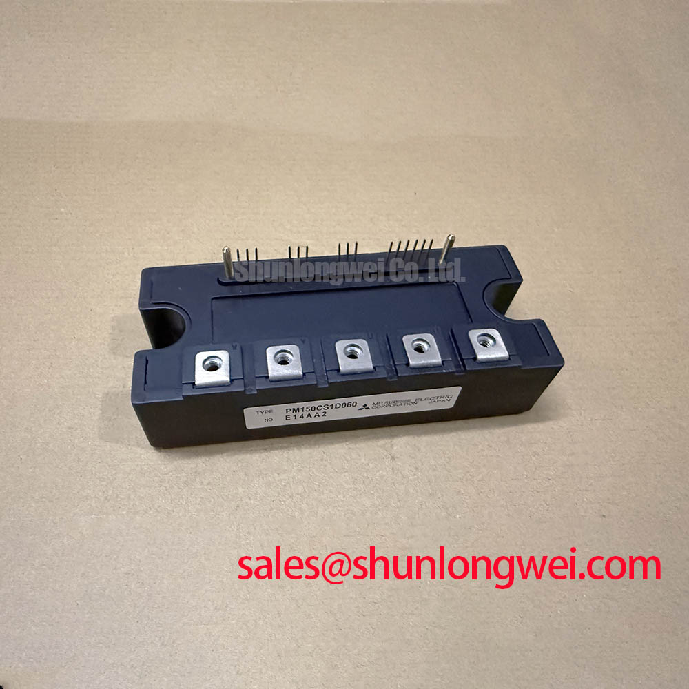
The PM150CS1D060 is a Mitsubishi Electric IPM module rated at 600.0 V and 150.0 A. Its specified package category is a Mitsubishi IPM Module. For a forklift or electric material-handling vehicle that has stopped during traction operation, these three values provide the first replacement-screening boundary: the voltage class, the current class, and the physical module format must match the original inverter design before any waveform tuning begins.
| Manufacturer | Mitsubishi Electric |
| Model | PM150CS1D060 |
| Module category | Mitsubishi IPM Module |
| Rated voltage | 600.0 V |
| Rated current | 150.0 A under specified conditions |
These are official product specifications. They do not, by themselves, establish the allowable switching frequency, motor current profile, inverter cooling capacity, or traction-system duty cycle. Those limits remain system-level design conditions and must be checked against the original controller, bus voltage, load profile, protection settings, and thermal path.
Start the mechanical inspection at the copper baseplate and heatsink interface because poor contact can distort the electrical test result by raising junction temperature during the first switching run. Place the module on a clean, rigid reference surface and inspect the heatsink contact area under direct lighting. Scratches, raised burrs, embedded debris, or a visible high spot can prevent the thermal interface material from spreading evenly across the active area.
The heatsink should present a stable, clean mounting plane without local distortion around the screw holes. A practical Design Consideration is to use a thin, continuous thermal interface layer rather than several disconnected patches. The final interface thickness is determined by the actual material, flatness, mounting pressure, and manufacturer instructions for the compound.
Apply the thermal compound with a controlled spreading method that avoids trapped air pockets. Excess material can migrate toward the baseplate edge and contaminate nearby surfaces, while insufficient material leaves dry areas that are difficult to see after assembly. The aim is not to create a thick thermal cushion. The aim is to fill microscopic surface irregularities while maintaining broad, even contact between the module baseplate and heatsink.
Use diagonal, progressive tightening so the baseplate settles onto the heatsink without concentrating force at one corner. Tightening one fastener fully before engaging the others can bend the baseplate locally or leave a section with incomplete thermal contact. The exact torque is a mechanical assembly value governed by the fastener size, washer arrangement, heatsink construction, and approved mounting instructions. It should be controlled with a calibrated tool rather than estimated by hand.
After mounting, inspect the assembly for rocking, corner lift, or a visible gap along the baseplate. If the heatsink is removed for correction, replace contaminated thermal compound rather than spreading the old material again. A second inspection is also useful when a module passes a cold electrical test but develops abnormal temperature rise during a short, controlled switching test.
Field Alert: De-energize the inverter and confirm the DC link is discharged before changing the module, gate cable, or busbar connection.
Heatsink flatness also affects waveform tuning indirectly. As temperature rises, switching behavior can shift and the protection circuit may respond differently from the cold bench condition. Keep the temperature measurement point and probe arrangement consistent while comparing the first waveform with the known-good phase. Minimize probe ground lead length and keep the measurement loop away from the power commutation path so the oscilloscope does not display avoidable pickup as a device fault.
For an industrial forklift traction inverter, the mechanical interface must also tolerate repeated vibration and thermal cycling. The busbar should be supported independently where the cabinet layout allows it, so its weight and vibration do not load the module terminals. The original creepage and clearance arrangement should be preserved around the power terminals and control connector. IEC 60664 insulation coordination principles are relevant when the equipment designer evaluates spacing, pollution conditions, and the enclosure environment; the component itself should not be treated as an independent system certification.
Benchtop Waveform Tuning: Mitigating Stress via Baseplate Convexity Compensation and Screw on PM150CS1D060
Baseplate curvature must be handled as an interface problem, not corrected by forcing the module down with excessive fastener load. Place the heatsink on a stable surface, clean both contact faces, and confirm that the screw heads, washers, and threaded holes are free from material that could alter the seating height. A distorted heatsink can reproduce the same thermal symptoms as a curved module baseplate, so both parts should be checked before deciding which part requires replacement.
When the module and heatsink are joined, use a cross-pattern sequence with small, repeated increases in torque. This allows the baseplate to settle progressively and helps distribute the thermal compound across the contact area. The selected TIM supplier, surface condition, fastener system, and thermal design determine whether the resulting interface is suitable.
Void elimination depends mainly on surface preparation and application technique. Do not use a thick layer to compensate for a visibly uneven heatsink. Correct the mechanical surface or replace the unsuitable heatsink, then reapply the compound. If a removed module shows a sharply dry region on one side and a heavy compound ridge on the other, treat that pattern as evidence requiring further mechanical inspection rather than as a direct diagnosis of semiconductor damage.
Before reconnecting the drive, verify the terminal identity against the original inverter drawing and cable labels. Power terminals, motor-phase connections, control supply, fault output, and gate-drive connections must not be inferred solely from physical proximity. Confirm connector keying and cable orientation, then inspect for bent contacts, loose crimps, damaged insulation, and contamination. The system integrator should verify the required control supply and protection sequence from the original equipment documentation.
Busbar fastening deserves the same care as heatsink installation. A rigid copper link can transfer vibration directly into the module terminal if it is not supported. Align the busbar without using the terminal screw to pull a misaligned conductor into position. The fastening method should maintain low-resistance electrical contact while avoiding mechanical stress on the module body. After assembly, check that the busbar cannot move enough to rub insulation or change its clearance during equipment vibration.
For replacement planning, engineers may evaluate the related PM150CSE060 as a separate, objectively comparable device in the same product family. It should not be treated as an automatic substitute. Confirm its electrical ratings, control interface, mechanical dimensions, protection behavior, and the original inverter's gate-drive requirements before considering it for a repair bill of materials.
When the traction stage includes a separate rectifier or auxiliary conversion stage, the system comparison may also involve PMH150CS1D060. That reference concerns topology-level selection and should not be interpreted as evidence that the device is a direct replacement for the PM150CS1D060.
Transient Dynamics and Electrical Design: Dynamic Gate Impedance Control for Robust PM150CS1D060 Operation
Gate-loop impedance and commutation layout determine how quickly a switching command reaches the semiconductor and how much unwanted voltage appears at the gate during the opposite device's transition. Keep the gate-drive loop compact, route the command and return paths together, and separate the control return from high-current power paths. The target is controlled switching with sufficient dead time to prevent cross-conduction, while avoiding unnecessary delay that increases switching loss.
High dv/dt can couple through the Miller capacitance and lift the off-state gate voltage. An active Miller clamp can provide a low-impedance path during the vulnerable part of the transition, but its timing and current capability must match the actual gate-charge behavior of the installed module and driver. Treat the clamp as a system design function rather than as an automatic feature of the power module. Confirm operation with an isolated differential probe and compare the gate-to-emitter waveform at the module terminals, not only at the driver output.
Some industrial gate-drive designs evaluate a negative off-state gate bias, including values in the range of −5 V to −15 V, as a Design Consideration for suppressing dv/dt-induced turn-on. This range is not an official PM150CS1D060 rating supplied in the product data provided here and must not be applied without checking the driver, insulation system, gate-emitter limits, startup sequence, and fault behavior. The final bias is determined by the complete gate-drive design and verified under the worst switching conditions.
Dead time should be established from measured device delay, driver propagation behavior, temperature, load current, and the reverse-recovery behavior of the complementary freewheel path. A short dead time can increase the risk of shoot-through; an unnecessarily long dead time can increase diode conduction and associated loss. Tune it while monitoring both switch-node voltage and gate-to-emitter voltage, then confirm the result over the operating conditions used by the forklift traction controller.
Reverse recovery softness in the freewheel diode affects the current transient and the radiated and conducted noise generated by the commutation loop. The softness factor is a diode characteristic, not a universal property that can be assigned to the PM150CS1D060 without the applicable device data. During troubleshooting, inspect the switch-node ringing, gate perturbation, and DC-link current transition together. A change in one trace alone is not enough to identify the source of the disturbance.
Bootstrap supplies require particular attention when the high-side driver is used. The bootstrap capacitor must receive adequate refresh time and the startup sequence must keep the driver within its operating conditions. Mitsubishi Electric's Mitsubishi DIPIPM Bootstrap Circuit Design application note provides relevant guidance for evaluating bootstrap operation, charging paths, and high-side drive behavior. Apply that information to the actual driver and circuit topology rather than assuming every IPM control interface is identical.
For a repaired forklift inverter, test the gate signal first at low-energy conditions, then raise the electrical stress in controlled stages while observing the switch node, phase current, DC-link disturbance, and module temperature. Keep the power-loop inductance low according to the system layout objective, place the snubber or clamp network according to the measured overshoot path, and verify peak voltage margins against the 600.0 V rating during switching tests. The 150.0 A rating must likewise be interpreted with the specified thermal path and operating conditions rather than used as a standalone continuous-current guarantee.
When reviewing newer wide-bandgap switching strategies around an existing traction platform, the Wide Bandgap Revolution engineering guide can help frame the differences in switching speed, layout sensitivity, and protection requirements. Those technologies are not interchangeable with this Mitsubishi Electric IPM without a complete electrical, mechanical, thermal, and control redesign.