Content last revised on September 15, 2026
PM300RSE060 600 V 300 A Intelligent Power Module: Ratings and Application Checks
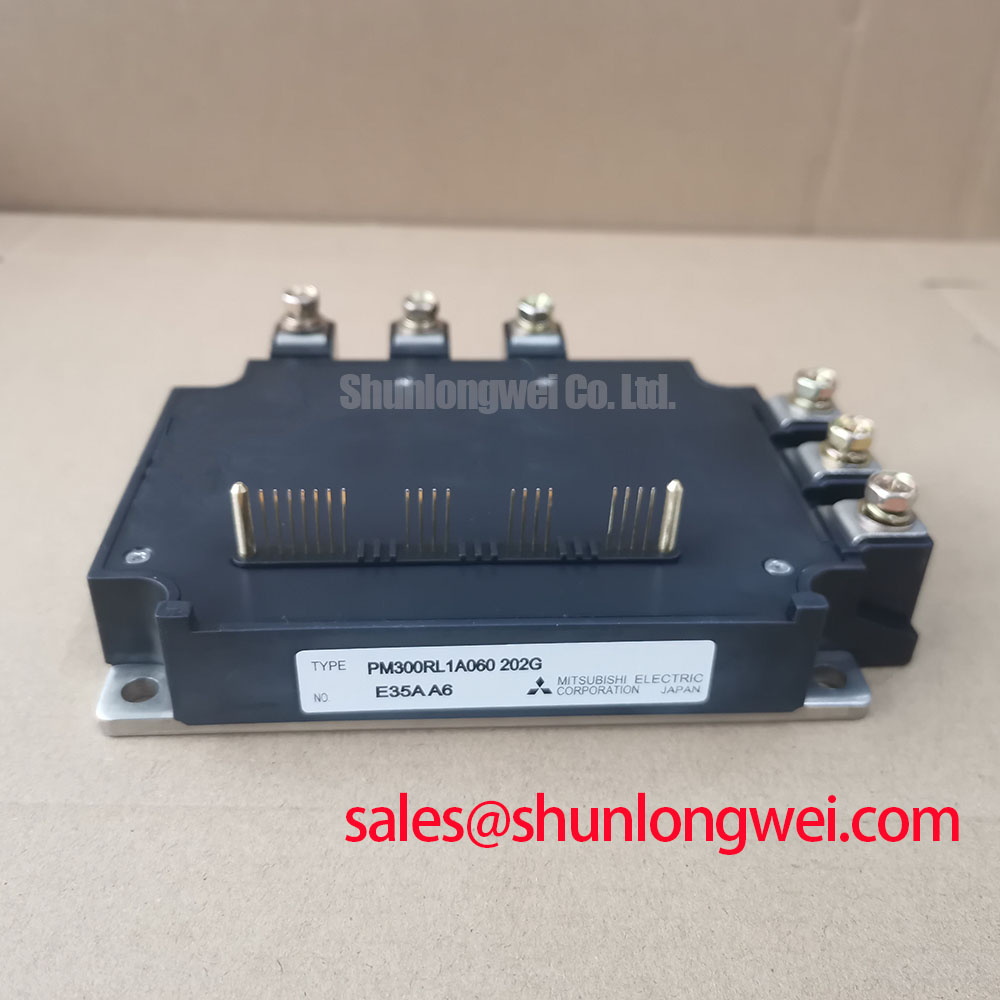
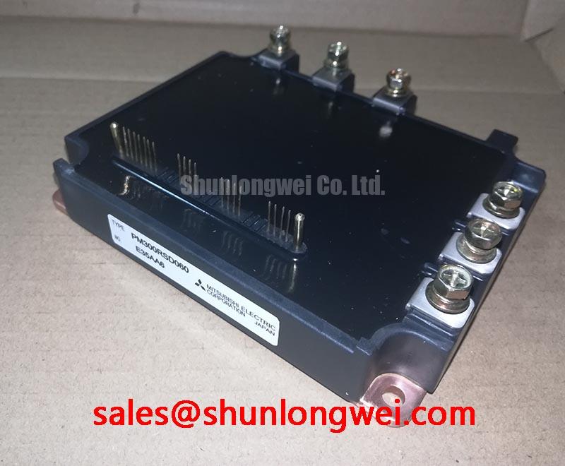
With the equipment isolated and the DC link discharged, first verify that the installed unit is marked PM300RSE060, then compare its power terminal arrangement and control connector orientation with the original assembly documentation before connecting a meter or drive harness. This Mitsubishi Electric intelligent power module is rated at VCES = 600 V and carries an official inverter collector current rating of 300 A; its brake circuit collector current rating is 100 A. The official logic control supply specification is VD = 15 V, while the typical specified collector emitter saturation voltage is VCE(sat) = 1.7 V. Its stated isolation rating is 2500 Vrms for 1 minute at AC 60 Hz.
These ratings identify the electrical boundary of the PM300RSE060 itself. They do not establish a permitted DC bus voltage, switching frequency, overload duration, fuse selection, snubber value, or thermal capability for a particular inverter. Those results depend on the complete converter layout, cooling assembly, gate drive behavior, control timing, fault response, and measured operating waveform.
| Official specification | PM300RSE060 rating |
|---|---|
| Collector emitter voltage | 600 V |
| Collector current rating, inverter | 300 A |
| Collector current rating, brake | 100 A |
| Logic control supply voltage | 15 V |
| Typical collector emitter saturation voltage | 1.7 V |
| Isolation voltage | 2500 Vrms, 1 minute, AC 60 Hz |
| Integrated protection logic | Over current, short circuit, over temperature, under voltage |
💡 Bench Tip: Use ESD controlled handling and record cold state meter observations against a known good assembly of the same equipment before treating any diode mode reading as a pass or fail result.
Preventing Spurious Faults: DC Link Capacitance Bank Layout and Low ES Guidelines for PM300RSE060
A PM300RSE060 installation should be assessed from the current loop outward, beginning at the DC link capacitor bank, the module power terminals, and the busbar return path. During switching, the voltage seen at the module is influenced by the DC bus voltage plus the product of stray loop inductance and the rate of current change. This relationship is an Engineering Calculation principle, not an additional PM300RSE060 rating. A long or asymmetric path between the capacitor bank and the module can add turn off overshoot, create ringing, and cause the integrated protection system to respond to a condition that the control engineer did not intend.
Design Consideration: place the commutation capacitance so that the outgoing and returning high current paths remain physically close and have a short shared loop. A laminated or planar busbar arrangement is commonly evaluated because adjacent opposing conductors reduce loop area. The final capacitor selection, physical geometry, clearance distances, and busbar construction must be verified by the system engineer with measurements at the actual switching operating point. The 600 V collector emitter rating is an official device boundary, not a substitute for observing the switching peak at the module terminals.
When a commercial string inverter or micro grid energy storage converter reports intermittent over current, under voltage, or short circuit events only at particular load transitions, inspect the capacitor connections for unequal path length, loose fastening, heat discoloration, and signs that a power conductor has shifted from its original position. Also check whether the measured DC link ripple and terminal overshoot change when a known good capacitor bank is connected. A repeating high frequency ringing pattern can point toward layout parasitics, a degraded capacitor path, gate drive interaction, or a measurement setup issue. It should not be assigned to one cause without waveform verification.
The PM300RSE060 includes over current, short circuit, over temperature, and under voltage protection logic. The external system must still coordinate its controller response with those protections. A nuisance trip investigation should therefore capture the logic supply rail, the fault output where accessible in the equipment documentation, DC link voltage, phase current, and switching node waveform on the same time reference. This separates a genuine load event from a gate drive supply disturbance or an overshoot related event.
For engineers comparing legacy inverter assemblies, CM300DXDX1-24A can be reviewed as a separate 300 A class reference. Equivalent current class does not confirm mechanical, control, protection, pinout, or circuit compatibility. Each replacement evaluation requires the original equipment schematic and physical interface to be checked.
Field Diagnostics & Commissioning: PCB Gate Loop Layout Symmetry in PM300RSE060 Topologies
Before commissioning a repaired power stage, confirm the control connector seating, the 15 V logic supply at the specified control interface, and the integrity of the control ground route defined by the equipment documentation. The PM300RSE060 is an intelligent power module, so its gate drive and protection functions are integrated. It is not appropriate to assume that externally accessible control pins provide the same test access, gate resistance path, or auxiliary emitter arrangement found on a discrete IGBT assembly.
Design Consideration: keep sensitive control return paths separated from high current power return paths wherever the host PCB and module interface permit. Shared impedance can couple switching current into a control reference, causing apparent gate signal movement or unstable protection behavior. A layout review should trace the return current physically, not only follow the schematic symbol. The goal is to reduce mutual coupling between the switching path and the low level control path, then verify the result with differential probing at the relevant equipment test points.
Freewheeling diode reverse recovery can also shape switching node behavior. A rapid recovery transition can excite the busbar, capacitor, and module connection inductances, which may appear as radiated noise or ringing at the controller. Snubber networks can be evaluated as a Design Consideration when measurements show that the existing hardware does not adequately control the observed transient. Their values and dissipation must be established from the actual converter waveform and thermal conditions, rather than copied from an unrelated 600 V inverter.
During a static incoming check, diode mode readings can be useful for comparing polarity paths with a known good unit, provided the test method follows the original circuit context and all stored charge has been removed from surrounding capacitors. A reading that differs from another assembly may indicate a module problem, an external parallel path, a meter limitation, or an unpowered control circuit interaction. Isolate only as far as the service documentation permits, then repeat the comparison under the same conditions.
The bootstrap supply arrangement in an inverter must be considered alongside the PM300RSE060 control supply and the host control board sequence. Mitsubishi Electric’s DIPIPM™ Bootstrap Circuit Design note provides general industry reference material on bootstrap circuit behavior. Engineers should confirm whether that guidance applies to their own controller architecture and original equipment circuitry before using it as a test basis.
Assembly Integrity & Layout Architecture: Implementing High Speed Fault Management for PM300RSE060
The PM300RSE060 declares integrated over current and short circuit protection logic, but the supplied official data does not define a complete external desaturation implementation, fault blanking interval, soft turn off profile, or short circuit withstand time for a host system. Those values must not be inferred from the presence of protection labels. When reviewing a failed converter, inspect the controller schematic to establish whether the equipment relies on the module’s internal fault functions, an external current sensing circuit, voltage sensing, or coordinated protection layers.
Engineering Recommendation: design the fault path so it remains electrically quiet, directly referenced according to the original control scheme, and independently observable during commissioning. The system controller should capture the source of a trip where that capability exists. A trip caused by load current, a low control supply, an overtemperature indication, or an external interlock may require very different corrective work even when the equipment presents the same general fault code.
Soft turn off behavior is relevant because interrupting high current through a stray inductance can elevate collector emitter voltage. The control system should be validated for its response during abnormal switching conditions by measuring voltage and current together and comparing peak behavior against the applicable operating margins. Do not alter gate damping, protection timing, or snubber circuitry solely to eliminate a visible fault indication. An apparent improvement in fault frequency can conceal higher switching stress if the terminal waveform has not been checked.
Protection coordination also includes the DC link fuse and contactor strategy. The semiconductor fuse selection process is a system level engineering task that considers the available fault energy, clearing behavior, prospective current, conductor capability, and coordination with the module’s internal protection response. The PM300RSE060 official specifications listed here do not provide an I²t value or fuse part number. Procurement and repair teams should therefore preserve the original equipment protection design unless a qualified engineer has validated an alternative.
Mechanical assembly requires equally careful control. Check the mating heatsink surface for flatness, contamination, and evidence of uneven pressure before installation. Apply the mounting process specified by the original equipment manufacturer and verify that power terminals, control connectors, and insulation barriers are fully seated. The stated 2500 Vrms isolation specification applies under the stated official test condition; it does not certify the finished inverter enclosure, cabling, or site installation.
Transient Dynamics & Electrical Design: High Altitude Cosmic Ray Induced SEB Risk for PM300RSE060
No official PM300RSE060 field failure rate, cosmic ray susceptibility figure, single event burnout qualification result, altitude derating curve, or operating lifetime figure is provided in the available specification set. It would therefore be inaccurate to assign a FIT rate, predict service hours, or calculate a failure probability for this module at a particular elevation. The 600 V VCES value remains an official collector emitter voltage rating, while application voltage stress must be established from the converter’s measured switching behavior and environmental requirements.
Design Consideration: projects intended for elevated installations should evaluate environmental conditions, DC bus stress, cooling capability, insulation coordination, surge environment, and required site standards as a complete system. Reduced air density can affect the enclosure and external insulation arrangement; it is not evidence by itself that the PM300RSE060 has a stated altitude rating. Likewise, semiconductor behavior under terrestrial radiation exposure must be addressed using applicable manufacturer documentation and project reliability requirements rather than generalized numerical claims.
For a commercial string inverter or micro grid energy storage system, a practical investigation starts with recorded fault time, DC bus condition, heatsink condition, ambient data, controller logs, and a terminal waveform taken with an appropriate high voltage differential probe. Compare the observations against a known stable unit operating under the same converter settings. If repeated faults correlate with switching transients, review the DC link layout and control return path before treating the module as the sole source of the event.
For broader guidance on gate drive, thermal paths, fault response, and topology level checks, see IGBT Design & Integration. The final acceptance decision should be based on the original equipment documentation, controlled bench measurements, and the stated ratings of the PM300RSE060.