
Content last revised on September 28, 2026
PM400DHA060 Assembly Integrity and Layout Assessment
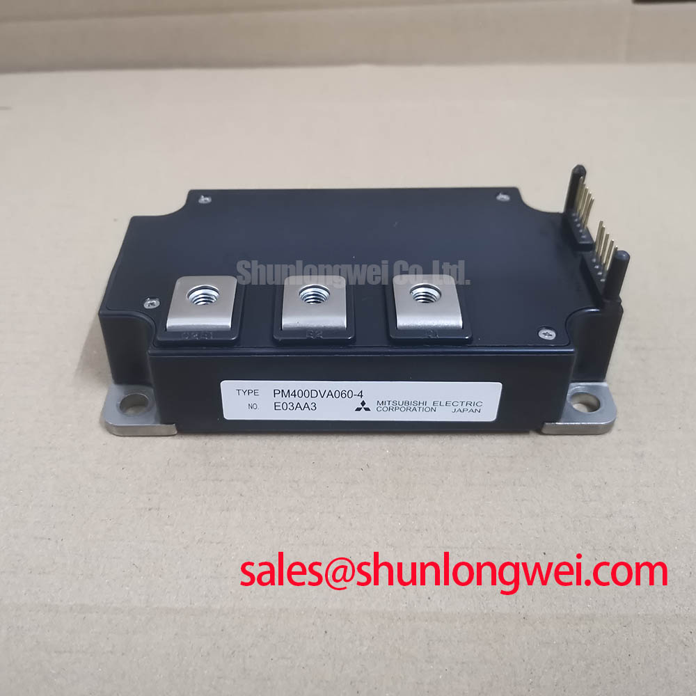
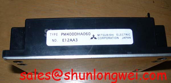
Isolate the DC link, then compare the installed module’s nameplate and terminal layout with the replacement documentation before removing any connections. PM400DHA060 is a Mitsubishi Electric intelligent power module with a 600 V voltage rating and 400 A current rating (Official Specification). Those ratings establish an initial screening boundary; they do not, on their own, confirm fit, drive compatibility, or safe operation in a particular converter.
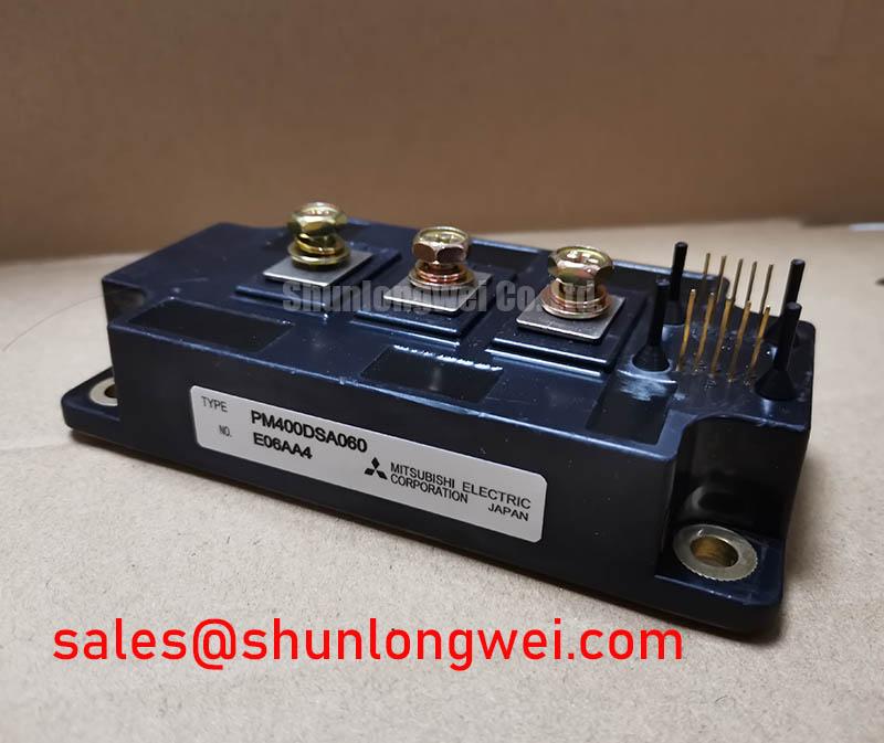
Begin a replacement assessment with the equipment drawing rather than the current rating alone. Record the installed module’s terminal identification, control connector orientation, mounting pattern, cooling interface, and surrounding clearance. Check each item against the applicable PM400DHA060 manufacturer documentation and the original equipment design. An IPM contains control and protection functions whose external connections must be treated as module-specific; a visually similar power module is not necessarily electrically interchangeable.
The 600 V rating (Official Specification) is a device limit, not a recommended DC-link operating voltage. As a Design Consideration, the system engineer should assess the highest bus voltage under normal operation and credible transients, then measure switching peaks at the installed layout. Clearance around exposed conductors must likewise be evaluated against the equipment’s insulation design and applicable installation requirements. Neither a voltage margin nor a clearance dimension can be assigned from the two headline ratings alone.
For a wind turbine full-scale converter, PM400DHA060 could be considered only after the converter’s actual voltage, current waveform, cooling arrangement, and protection interface have been checked. Equipment scale does not establish module suitability: the number of converter paths and the electrical duty of each path matter. At sites where altitude is a concern, treat environmental derating and radiation-related failure mechanisms as Design Considerations requiring application-specific manufacturer guidance and qualified reliability data. The supplied PM400DHA060 ratings do not support a numerical FIT, single-event burnout, or altitude limit.
During fault assessment, compare photographs and measurements from the affected position with a known-good position where one is available. Look for uneven mounting contact, discolored terminals, damaged control connections, and changes in busbar routing. These observations guide further tests but do not identify a failure cause by themselves. Mitsubishi Electric’s power semiconductor and high-power module resources provide manufacturer context for checking module documentation before changes to an existing assembly.
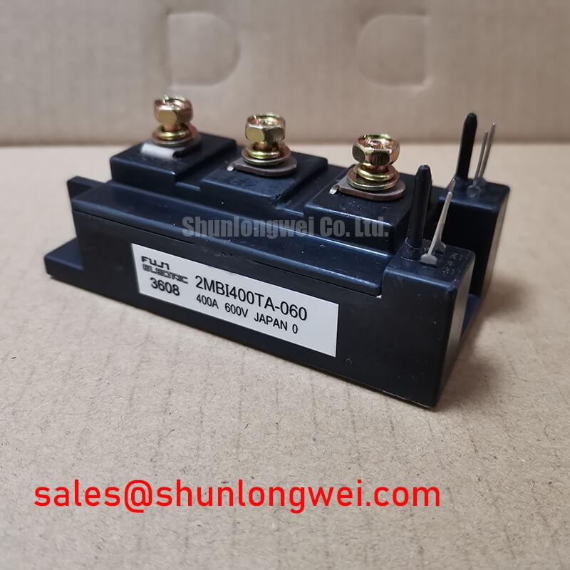
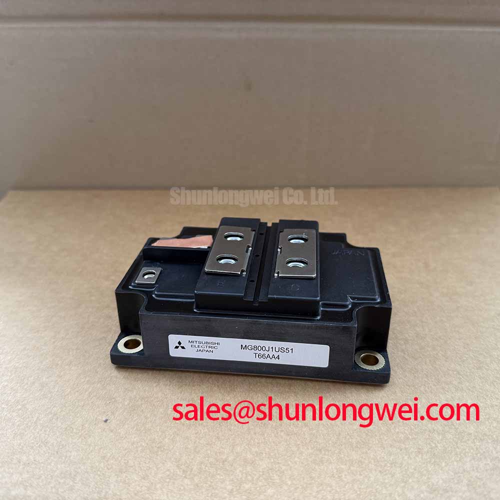
When evaluating alternatives, compare topology, terminal assignment, control supply, protection behavior, mechanical interface, and cooling requirements before electrical ratings. The CM100DY-12E is a separate module to assess against those requirements, not a confirmed direct replacement for PM400DHA060. A sourcing comparison cannot substitute for review of the equipment schematic and manufacturer data.
PM400DHA060 Thermal Interface and Fault Coordination
Clean and inspect the heatsink contact area before seating the module. Check for burrs, old interface material, contamination, or visible distortion that could prevent even contact. Apply the thermal interface material using the method specified for the module and heatsink assembly, then tighten the mounting fasteners in the documented sequence and to the documented torque. Without those instructions, a particular paste thickness or torque must not be presented as a PM400DHA060 requirement.
As a Design Consideration, the purpose of interface control is to limit gaps and voids while preserving reliable mechanical seating. Adding material to compensate for a poorly prepared surface can make the thermal path less predictable. If a removed module shows an uneven contact pattern, inspect both mating surfaces and the fastening arrangement before attributing a temperature alarm to the semiconductor alone. Record heatsink temperature, load conditions, and cooling-system status so that a subsequent comparison is meaningful.
The 400 A current rating (Official Specification) should not be treated as a blanket allowance for surge or short-circuit current. Continuous current, transient overload, diode surge duty, and short-circuit withstand are different specifications, each dependent on the conditions stated in the relevant documentation. Designers coordinating a semiconductor fuse should compare its clearing behavior and energy let-through with the verified device and circuit limits across the expected fault paths. The headline current rating does not establish an I²t limit or guarantee that a fuse will isolate a fault before module damage.
A similar distinction applies to pulsed heating. Junction temperature during a brief load event depends on the starting temperature, pulse duration, losses, and transient thermal impedance. As an Engineering Recommendation, obtain the applicable loss and thermal-impedance data before assessing a peak-temperature margin; use measured operating conditions rather than assuming the heatsink temperature tracks the junction instantaneously. For repeated charge and discharge duty in a bidirectional DC-DC system, evaluate the actual thermal cycle against qualified module data instead of assigning an unsupported service-life figure.
Bench precaution: Do not disconnect a control or power connection until the equipment’s DC link has been isolated and verified discharged.
Benchtop Waveform Tuning Around the PM400DHA060 DC Link
After checking mechanical installation and control connections, examine the switching waveform at the module terminals under a controlled test condition. Measure the DC-link level and the turn-off peak with an appropriate high-voltage measurement setup; probe placement matters because a long measurement loop can add apparent ringing. Compare results between operating points and, where possible, against a known-good converter path. A peak that changes with load or switching speed calls for investigation of the commutation path, measurement setup, and control behavior rather than an immediate change of snubber parts.
As a Design Consideration, parasitic inductance in the capacitor-to-module loop contributes to turn-off overvoltage as current changes. Keep the outgoing and return current paths close and review the symmetry of the busbar and capacitor connections to limit that loop inductance. The system engineer should verify the resulting peak against the measured DC-link voltage and the module’s 600 V rating during switching tests. No universal inductance target or snubber capacitance follows from the PM400DHA060 headline specifications.
Pro Tip: Keep the busbar’s outgoing and return paths closely paired, then verify turn-off peak margin with controlled switching measurements before accepting a layout change.
Inspect local DC-link capacitor connections for loose joints, altered routing, and signs of heating. If a snubber or clamp is fitted, identify its values and connection points from the equipment schematic before replacing it or changing its layout. An MOV elsewhere in the equipment may participate in broader overvoltage protection, but its presence does not establish adequate suppression of the fast voltage peak at the module. Device-terminal measurements are needed to evaluate that distinction.
Control-side waveforms deserve a separate check. Common-mode movement during switching can disturb an optocoupler or digital-isolator signal path, depending on the drive board and its installation. As a Design Consideration, compare command, feedback, and fault signals at the points permitted by the service procedure, while maintaining the required measurement isolation. For background on off-state drive behavior, see Evolution of Negative Off-Bias Gate Drive Circuits; any bias scheme or gate-loop change must still be checked against the PM400DHA060 documentation and the installed control circuit.
PM400DHA060 Overcurrent Protection and Controlled Turn-Off
Confirm how the installed drive board detects and reports an overcurrent event before attempting a powered fault investigation. Trace the relevant supply, command, status, and fault connections against the equipment schematic and the module documentation. An IPM’s protection behavior must not be inferred from its voltage and current ratings. Detection thresholds, delays, reset conditions, and permitted fault tests require the applicable manufacturer data and equipment procedure.
Short-circuit protection is a coordination problem between detection, drive behavior, wiring, and the power circuit. A fast interruption can limit fault energy yet raise inductive turn-off voltage; a controlled turn-off strategy must therefore be validated against both current and voltage stress. As an Engineering Recommendation, review measured fault-response timing and voltage only under an approved test method. Do not assign a PM400DHA060 short-circuit withstand time or prescribe a turn-off sequence without a supporting specification.
If an overcurrent indication appears during commissioning, first confirm that the reported fault corresponds to the observed operating state. Review current-sensor output, control supply stability, connector seating, cooling-system status, and switching waveforms. A fault indication can reflect more than one condition, while an apparently clean command waveform does not rule out a power-path problem. Keep records of bus voltage, load state, temperature, and the exact point where each waveform was taken.
For a final integration check, compare the recorded conditions with the original equipment limits and the applicable Mitsubishi Electric documentation. Mitsubishi Electric’s semiconductor device resources provide a manufacturer starting point for documentation, but the installed converter’s schematic and test procedure determine which control signals and protection events can be assessed safely.