

Content last revised on September 18, 2026
PM400DSA060 Inspection and Bench Testing
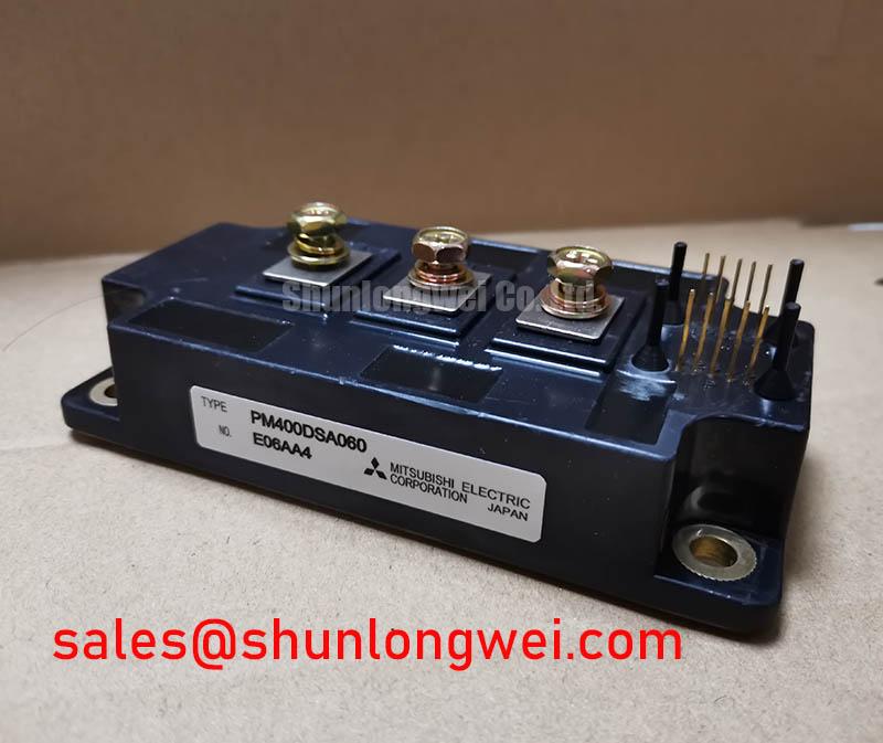
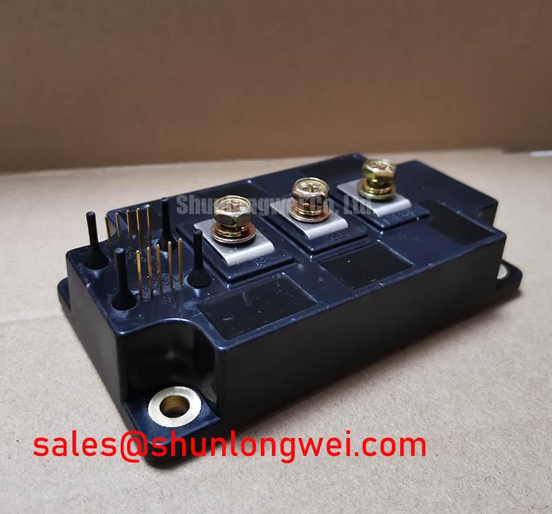
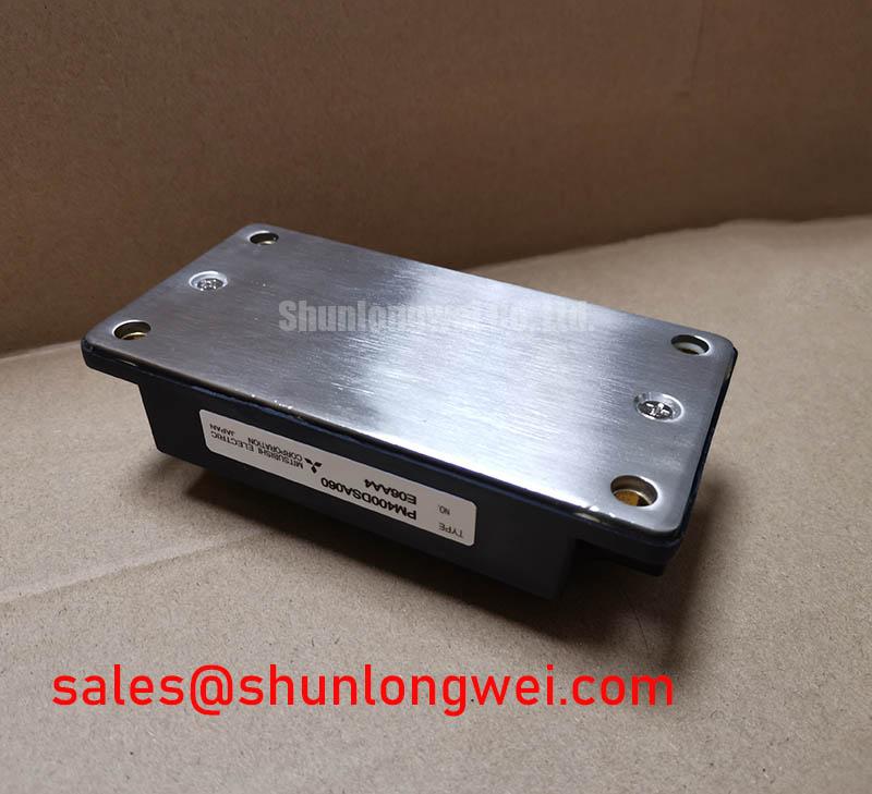
With the converter isolated and discharged, begin incoming inspection of the PM400DSA060 by checking the case, power terminals, control terminals, and mounting surface for damage, contamination, loose hardware, or signs of prior overheating before any energized test. This Mitsubishi Electric module is identified with an Official Datasheet Specification rating of 600.0 V and 400.0 A, supplied in a Mitsubishi IPM Module package classification. Confirm that these nameplate limits match the removed unit and the equipment documentation before treating it as a service candidate.
For cold testing, keep all external gate drive and DC link connections removed. A diode mode check between applicable power terminals can help identify a clear short circuit or an unexpected open path when compared against the original circuit documentation or a known good assembly. The reading itself is not a complete health certificate because parallel circuitry, internal topology, and meter test current affect the observed result. Gate to emitter checks should remain within the expected high impedance behavior of the circuit under test; any result should be reviewed after confirming that the control connector is fully isolated from the drive board.
💡 Bench Tip: Use ESD controlled handling and record cold state terminal readings before fitting the module, because later measurements are far more useful when compared with the same test setup and meter.
| Parameter | Value | Classification |
|---|---|---|
| Product model | PM400DSA060 | Official product identification |
| Manufacturer | Mitsubishi Electric | Official manufacturer identification |
| Rated voltage | 600.0 V | Official Datasheet Specification |
| Rated current | 400.0 A | Official Datasheet Specification |
| Package category | Mitsubishi IPM Module | Official product classification |
Benchtop Waveform Tuning: Mitigating Stress via Output Sinusoidal Filter vs dv/dt Reactor on PM400DSA060
Before changing hardware around a PM400DSA060 installation, capture switching waveforms at the module side and, where access permits, at the motor side using suitable high voltage differential measurement equipment. Long motor cables can behave as transmission lines rather than simple conductors. A mismatch between cable impedance and motor winding impedance can reflect the switching edge back toward the inverter terminals. Under unfavorable conditions, the voltage at a remote cable end can approach twice the applied inverter voltage step. That is a system behavior, not an additional voltage capability of the 600.0 V module.
A dv/dt reactor and a sinusoidal output filter address different observations. A reactor is commonly evaluated when the goal is to soften current and voltage edge behavior while preserving a pulse width modulated motor output. A sinusoidal filter is evaluated when the motor, cable insulation system, acoustic requirement, or measured waveform requires a substantially smoother output. The choice must follow measured cable length, motor characteristics, switching strategy, thermal limits, and control loop behavior. Neither part should be selected solely from the PM400DSA060 current rating.
Design Consideration: keep the switching current loop compact, place DC link decoupling according to the converter layout requirements, and keep measurement leads from becoming antenna loops. Excess inductance in the commutation path can add overshoot during turn off. Engineers should verify peak collector to emitter stress against the DC link voltage during controlled switching tests rather than infer safety from a nominal bus reading.
A metal oxide varistor can be considered as part of an enclosure level surge suppression approach when the transient source and coordination scheme have been defined. It does not replace proper DC link layout, gate drive protection, fuse coordination, or a measured assessment of repetitive switching overshoot. Review the varistor energy duty, wiring inductance, and disconnection method against the complete converter design. An MOV that is physically remote from the disturbance may have limited effectiveness at the module terminals.
During commissioning, compare the command signal, gate drive output, collector to emitter waveform, and motor terminal waveform. Ringing that changes materially when probe position changes can be a measurement artifact. Ringing that persists with a verified probing arrangement may indicate cable reflection, loop inductance, gate drive interaction, or an output filter compatibility issue. Isolate one variable at a time and retain waveform records with the DC bus condition, load state, cable arrangement, and probe method.
In rectifier and inverter assemblies, upstream power stages should also be checked as part of the fault boundary. The CM100DY-12E can be reviewed as a separate complementary power device reference when evaluating associated rectification or power conversion circuitry. It is not evidence of direct interchangeability with PM400DSA060; terminal assignment, electrical ratings, drive arrangement, thermal interface, and protection behavior require independent verification.
Assembly Integrity & Layout Architecture: Implementing Galvanic Gate Drive Isolation, Reinforced for PM400DSA060
Start assembly verification by matching every control terminal to the equipment schematic and the applicable manufacturer terminal drawing. Do not infer a terminal function from connector position, color coding, or a visually similar module. The system integrator should verify whether the installed drive topology uses a dedicated auxiliary emitter return, a shared emitter reference, or another control return arrangement before routing any gate drive wiring.
Galvanic isolation belongs to the gate drive system architecture rather than being established by the PM400DSA060 voltage and current ratings alone. Where the equipment safety concept calls for reinforced isolation, the isolator, PCB creepage and clearance, connector system, contamination environment, transformer or digital isolator, and test requirements must be reviewed as one barrier. A requirement such as isolation above 5 kV or common mode transient immunity above 100 kV per microsecond must be confirmed from the selected gate driver documentation and the complete insulation coordination assessment. These figures must not be attributed to this module without an official module specification.
For industrial drive boards using optocouplers or digital isolators, inspect the physical separation between high energy power routing and the sensitive gate control path. Design Consideration: routing should minimize common mode coupling into the isolated receiver and prevent the power return current from sharing a sensitive control reference. Verify the result with switching tests under relevant load and bus conditions, observing whether gate voltage remains stable during the opposite switch transition.
The module mounting face and heatsink deserve the same discipline as the electrical layout. Clean both surfaces, remove particles, use the thermal interface material specified by the equipment service procedure, and tighten fasteners in a balanced sequence. Mounting torque, thermal compound thickness, flatness criteria, and mounting hardware are system and mechanical interface requirements unless stated by the applicable product documentation. Review the practical framework in The Advanced Thermal Management Revolution when assessing heat transfer paths and service related thermal interface issues.
Fast semiconductor fuse coordination should be assessed from the complete fault path. Fuse clearing behavior, available fault current, DC link energy, conductor inductance, contactor response, and the converter protection sequence determine whether a fault is isolated effectively. Engineers should compare the fuse time current and I²t information with applicable semiconductor surge and protection information from authoritative component documents. It is not valid to claim subcycle protection performance from the PM400DSA060 rated current alone.
For manufacturer level device family information, consult Mitsubishi Electric Power Semiconductors and High Power Modules. This supports a disciplined separation between official module data and system level assumptions made during repair or retrofit work.
Field Diagnostics & Commissioning: High Altitude Cosmic Ray Induced SEB Failure in PM400DSA060 Topologies
A converter installed above 2000 m should not be evaluated by assuming that sea level clearance, cooling, transient behavior, and environmental stress remain unchanged. Reduced air density can affect cooling and external insulation coordination, while the installation standard, enclosure construction, contamination level, and local service requirements determine the appropriate assessment. The PM400DSA060 official ratings supplied here are 600.0 V and 400.0 A; they do not establish an altitude derating curve, an insulation coordination rating, or a guaranteed operating condition at altitude.
Single event burnout is a high risk reliability topic. No sourced FIT rate, terrestrial neutron susceptibility value, cosmic ray failure estimate, or altitude specific lifetime figure is provided for this product here. A numerical failure in time calculation would therefore be unsupported. Design Consideration: where the equipment owner identifies altitude or radiation related reliability as a concern, evaluate DC bus operating conditions, transient peaks, temperature, and protection response using the applicable manufacturer evidence and equipment level reliability process.
Commissioning should remain evidence based. Review recorded fault codes, inspect DC link connections, compare all phase current sensor paths, and capture the voltage and gate signals at the instant protection reacts. A failed power stage can result from several interacting conditions, including a load side fault, a drive timing problem, loss of cooling, insufficient clearance, a fuse coordination problem, or excessive switching stress. Avoid assigning a single cause until the signal path and power path have each been examined.
Terminal creepage and clearance must be checked against the actual voltage class, enclosure pollution conditions, altitude requirements, and governing equipment standard. Keep conductive debris, carbonized residue, moisture paths, and unsecured control wiring away from the module connection area. Clearance is a physical insulation path requirement, while waveform overshoot is an electrical switching phenomenon; both must be controlled, but one cannot compensate for the other.
A high speed rail or heavy freight locomotive traction inverter can be considered as a compatibility assessment example only where its original electrical architecture is documented. The service engineer should verify the original converter voltage class, cooling interface, connector arrangement, gate drive logic, mechanical fit, and protection interlocks. The stated PM400DSA060 rating alone is insufficient to establish suitability for a traction inverter repair.
Additional manufacturer technology context is available from Mitsubishi Electric Global Semiconductor Device Technologies. Use the original equipment documentation and applicable product documentation as the controlling sources for any high altitude qualification decision.
Benchtop Waveform Tuning: Mitigating Stress via Kelvin Emitter Connection on PM400DSA060
Do not assume that PM400DSA060 provides a Kelvin emitter terminal unless this is confirmed from the original terminal drawing and the equipment schematic. A Kelvin emitter connection, where present in a power module system, is a low current gate drive reference separated from the main high current emitter return. Its purpose is to reduce the influence of common emitter inductance on the gate loop. Whether the module and existing drive board support this arrangement is a product specific interface question that must be verified before any rewiring.
When a verified auxiliary emitter path is available, route the gate and its return as a close coupled control pair and keep that pair separate from the main power current return. This is an Engineering Recommendation based on minimizing mutual coupling that can distort the effective gate voltage during high current transitions. The final routing and gate damping selection are system determined and should be validated through measured switching waveforms, protection behavior, and thermal testing.
Where the existing equipment does not provide a verified Kelvin reference, preserve the original approved return architecture rather than creating an unvalidated connection. A modified gate return can alter turn on and turn off behavior, protection thresholds, and noise susceptibility. Inspect the gate drive board for damaged isolation components, lifted tracks, connector stress, and unintended return paths through shields or mounting hardware before declaring the module defective.
For a potential hardware replacement review, SKIIP37AC12T4V1 can be examined as a separately identified power module option. It should only enter an engineering comparison after a documented review of topology, voltage and current ratings, terminal arrangement, control interface, mechanical envelope, cooling requirements, and protection compatibility. A model number reference is not a direct replacement instruction.
After reassembly, begin with the equipment’s approved low energy commissioning procedure where available. Verify gate command timing, phase symmetry, DC link behavior, protection response, and temperature monitoring before applying the intended operating load. This process creates traceable evidence for whether the PM400DSA060 installation, surrounding drive circuit, output network, and cooling assembly are working together within the boundaries established by the equipment design.