Content last revised on September 15, 2026
PM50RSA120 Circuit Protection & Reliability: Reviewing Gate-Drive and Miller-Effect Behavior
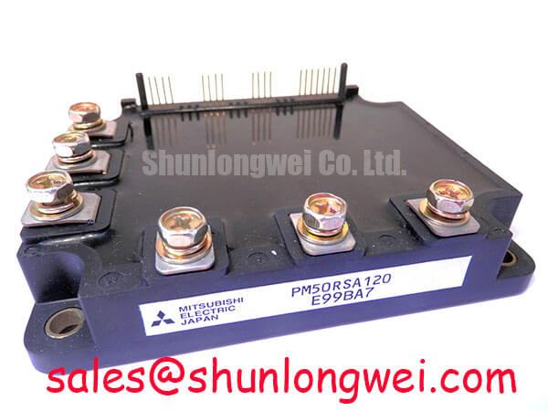
Before connecting a replacement module, isolate the DC link, inspect the terminal area for heat discoloration or cracked moulding, and verify that the inverter documentation calls for PM50RSA120 electrical ratings. This Mitsubishi Electric intelligent power module is specified at VCES 1200 V, IC 50 A DC at TC = 25°C, and VCE(sat) 2.3 V typical. Its stated 2500 V isolation voltage and 100 A minimum short-circuit current parameter are official datasheet specifications that should be checked against the original drive control and protection architecture before installation.
The PM50RSA120 Mitsubishi Electric IPM is commonly evaluated in three-phase industrial inverter assemblies where a 1200 V switching boundary and integrated protection functionality are required. A 400 V or 480 V AC input system can generate a substantially higher DC-link voltage than its line-voltage label suggests, particularly during regenerative operation. The official 1200 V collector-emitter rating provides the device voltage boundary, not permission to omit measurement of real switching overshoot.
| Official specification | Value | Integration relevance |
|---|---|---|
| Collector-emitter voltage, VCES | 1200 V | Voltage withstand boundary for the power switching section |
| Collector current, IC | 50 A DC at TC = 25°C | Continuous current reference requiring thermal-system verification |
| Collector-emitter saturation voltage, VCE(sat) | 2.3 V typical | Official reference for conduction loss assessment |
| Short-circuit current parameter, SC | 100 A minimum | Protection-related parameter requiring review of the complete fault-response system |
| Isolation voltage, VISO | 2500 V | Isolation rating to be considered with the complete equipment insulation system |
When an inverter leg is switching, a rapid collector-voltage transition can couple through the IGBT capacitances and disturb the gate potential of the opposite switch. In a practical repair inspection, this risk is investigated by probing the gate-emitter waveform and collector-emitter waveform at the module connections, using measurement practices appropriate to the inverter voltage. A gate pulse that appears during the opposing device transition can indicate that the gate return path, driver reference, clamping path, or probing arrangement requires further examination.
The PM50RSA120 official ratings establish the voltage, current, saturation-voltage, isolation, and short-circuit-related boundaries listed above. They do not, from the supplied official parameter set, establish a mandatory negative gate-bias value, an internal active Miller-clamp topology, or a fixed allowable switching slew rate. Those details must be verified from the original equipment schematic and the complete Mitsubishi Electric documentation applicable to the installed drive.
Design Consideration: A dedicated, low-impedance gate discharge route can help resist Miller-induced turn-on where high switching-voltage transients exist. The gate driver, its local return connection, the control connector routing, and the power commutation loop should be evaluated as one system. Long shared return paths can allow a power-current transient to appear as an unintended gate-emitter signal. Engineers should use a controlled double-pulse or equivalent switching test to confirm that the measured gate waveform remains within the driver and module limits during both turn-on and turn-off.
For equipment repair, first compare the affected phase with a known-good phase where the hardware permits safe comparison. Look for unequal gate waveform ringing, an unstable protection indication, or a difference in collector transition shape. Any of these observations may indicate a connection, driver, decoupling, busbar, or load-path issue; none should be treated as proof of one isolated cause. Replacing an IPM without correcting the switching environment can leave the original stress mechanism in place.
💡 Pro Tip: Keep the DC-link commutation path physically compact and symmetric so turn-off inductive overshoot can be verified against the DC-link voltage during switching tests.
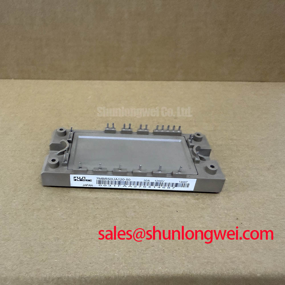
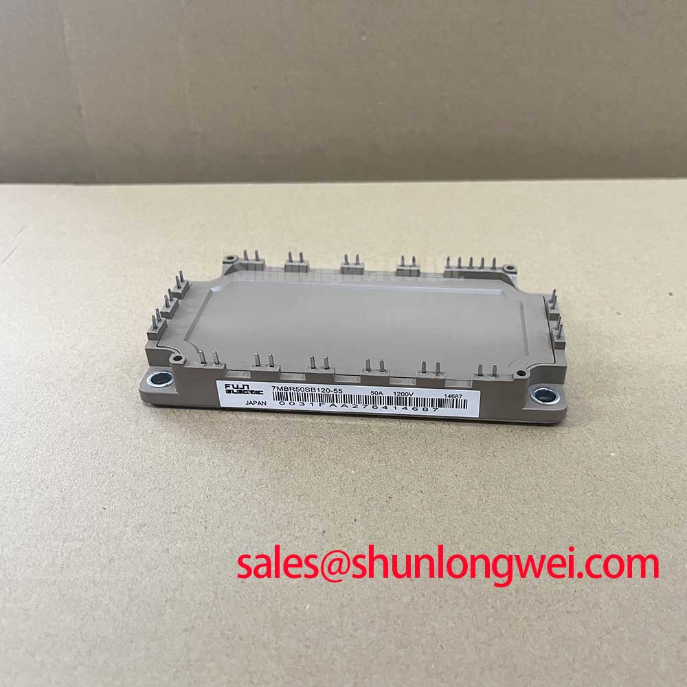
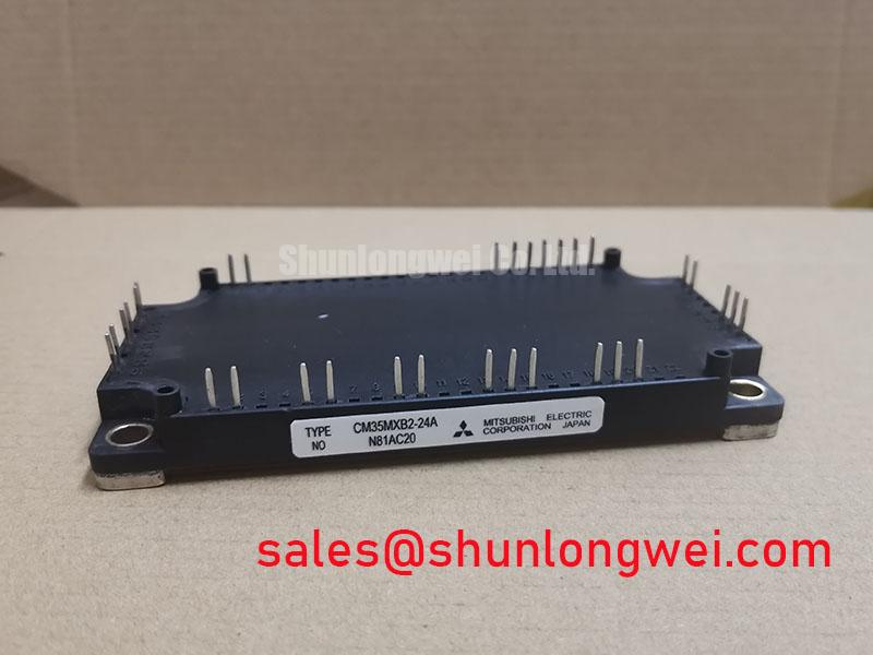
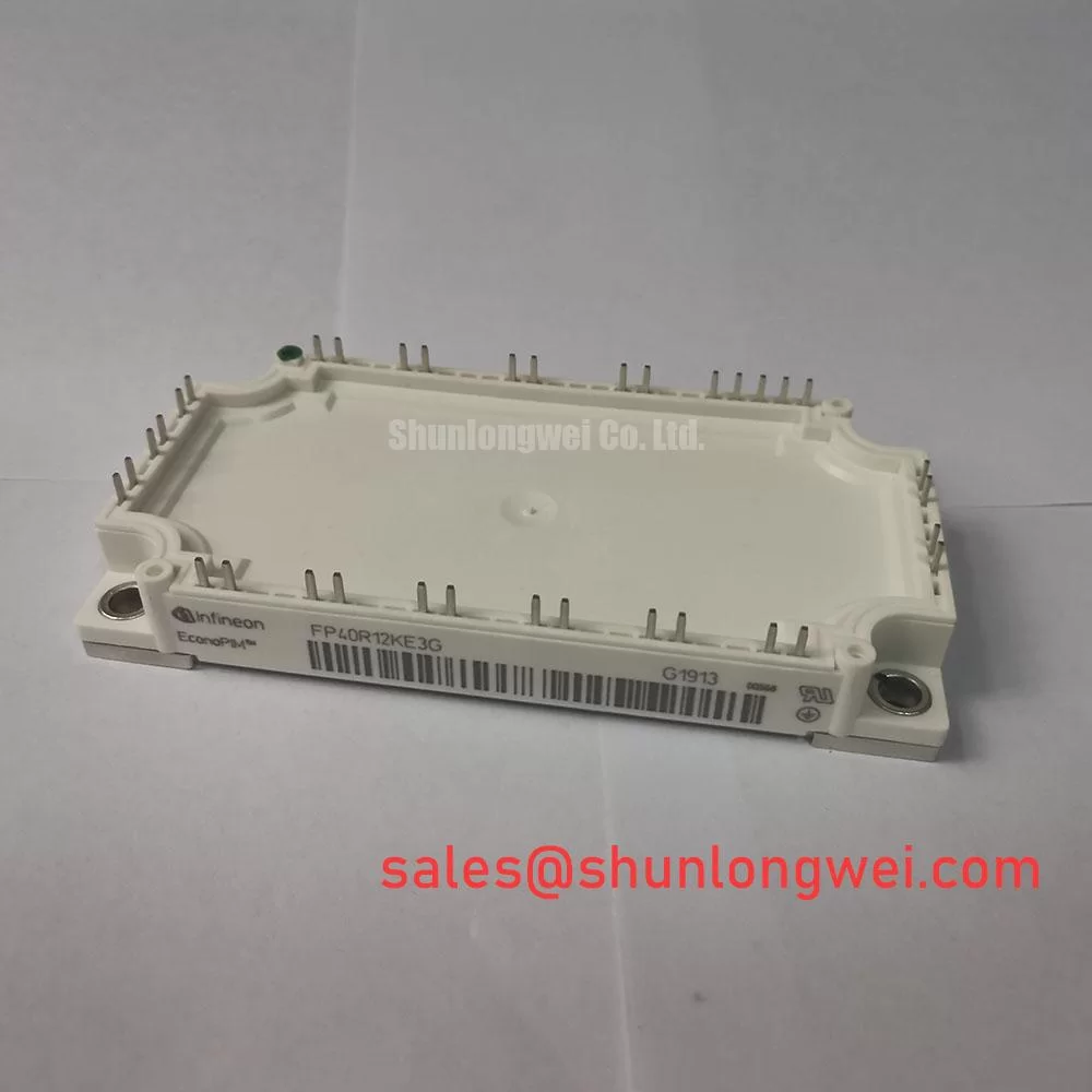
In traction inverter compatibility work, engineers may compare the electrical class and connection arrangement of alternative assemblies such as CM50DY-28H, but equal voltage and current labels alone do not establish a drop-in replacement. Pin functions, protection behavior, driver interface, thermal path, control logic, and mechanical mounting must each be verified from the equipment design.
Transient Dynamics & Electrical Design: Fault-Clearing Dynamics and Short-Circuit Protection
A short-circuit event must be treated as a system-level transient involving the IPM, gate-drive command, control supply, DC-link energy, motor-cable inductance, and fault-isolation hardware. The official 100 A minimum short-circuit current parameter is a meaningful protection-related reference for PM50RSA120 evaluation. It is not a published fault-clearing time, a guarantee of a particular desaturation implementation, or a substitute for verifying the controller’s response sequence.
Type-I and Type-II desaturation terminology is used differently across inverter platforms and driver families. For this reason, a maintenance engineer should not infer a specific sensing topology from the PM50RSA120 part number alone. Review the original controller diagram to determine whether fault recognition is generated inside the module, by an external driver circuit, through current sensing, or by a combination of these methods. The diagnostic output should then be checked through the controller input, firmware response, and gate-disable path.
Engineering Recommendation: Evaluate fault protection as a sequence rather than as a single threshold. The required sequence normally includes fault recognition, gate-command removal, controlled current interruption, DC-bus transient containment, and a controlled reset condition. A two-stage soft turn-off approach can be evaluated where the system must reduce inductive overvoltage while still removing gate drive promptly. The correct timing and gate-drive behavior are system-determined and must be validated against the module documentation and measured waveforms.
High-speed semiconductor fuse coordination also needs a full-system review. Fuse I2t behavior, available DC-link fault current, contactor response, cable impedance, and module surge capability must be considered together. A fuse is not automatically fast enough to protect a power semiconductor from every internal or external fault event. During commissioning, engineers should verify whether the IPM protection reacts before the fault energy reaches a damaging level and whether the DC-link protection safely handles the remaining energy after gate drive has been removed.
The Mitsubishi Electric application material on DIPIPM™ Bootstrap Circuit Design is a useful external reference for reviewing floating-side supply behavior and drive-circuit fundamentals. Its concepts should be applied only after confirming that the relevant circuit arrangement matches the installed PM50RSA120 system.
Benchtop Waveform Tuning: Reviewing Environmental and Switching Stress on PM50RSA120
The PM50RSA120 official parameter set provided here does not state an atmospheric-neutron qualification, a single-event burnout rate, a failure-in-time value, an altitude derating curve, or a cosmic-ray operating limit. No numerical reliability prediction for terrestrial neutron exposure should therefore be assigned to this module without an applicable manufacturer specification or a cited qualification source.
Design Consideration: Equipment intended for elevated locations can be reviewed for environmental and electrical operating conditions as part of the complete inverter validation plan. The system integrator should identify the actual installation altitude, DC-link operating range, transient exposure, cooling conditions, and required equipment standards. The voltage headroom must be confirmed from measured peak collector-emitter stress rather than estimated from nominal line voltage alone.
Benchtop waveform work remains valuable because it reveals stresses that are directly measurable. With the inverter secured and the test method reviewed for operator safety, observe the collector-emitter waveform, gate-emitter waveform, DC-link behavior, and fault output during representative loading transitions. Excessive ringing, irregular turn-off behavior, or protection activity that differs between phases may indicate a need to inspect busbar joints, capacitor connections, gate-return routing, driver-supply integrity, load cabling, and measurement setup.
A fast voltage probe with an unsuitable ground connection can itself create misleading ringing. Engineers should compare results using an appropriate isolated or differential measurement method and correlate the waveform with the actual switching command. This avoids changing a gate network or power layout based on a measurement artefact. The practical objective is to minimize parasitic loop inductance to suppress turn-off overshoot, then verify peak margins against DC-link voltage during controlled switching tests.
For broader context on switching behavior, semiconductor structure, operating mechanisms, and the boundaries between component ratings and application validation, consult The Ultimate IGBT Knowledge Base. It supports technical assessment but does not replace the PM50RSA120 documentation or the original equipment validation procedure.
PM50RSA120 Operational Boundaries: Evaluating Regenerative DC-Bus Voltage and Energy Management
During deceleration, a traction motor can return mechanical energy to the DC link. In electric material-handling and forklift low-voltage traction systems, the resulting DC-bus rise must be managed by the complete energy path: battery acceptance, charging state, bus capacitance, braking-chopper arrangement where used, ballast-resistor capability, wiring, and supervisory control. The PM50RSA120 1200 V VCES specification is a collector-emitter limit, not a published regenerative-energy absorption rating for the overall inverter.
A braking IGBT and ballast resistor, when present in the original architecture, should be assessed from the actual deceleration profile and the permitted DC-link operating window. The system engineering team should determine whether returned energy is absorbed by the energy source, dissipated through a braking path, or limited by motor-control behavior. Resistor thermal capability must account for repeated events and enclosure heat transfer, while the braking-switch layout should limit loop inductance so that switching transitions do not create avoidable voltage stress.
In a field investigation of overvoltage trips, record the DC-link waveform through acceleration release, commanded deceleration, direction reversal, and high-inertia load conditions. Compare the event with battery state, charge-system status, brake-resistor continuity, chopper command, and controller fault record. A rising DC bus can have several contributing factors, including limited energy acceptance, an interrupted braking path, incorrect control behavior, or measurement limitations. The evidence should guide the next test rather than assuming a single fault source.
Thermal integration also remains central to the stated 50 A DC rating at TC = 25°C. That current condition is not the same as a guaranteed current in an enclosed vehicle inverter. The heat sink, thermal interface, airflow or liquid-cooling arrangement, mounting flatness, fastening method, switching duty, ambient condition, and regenerative duty cycle determine the actual operating temperature. When integrating or repairing the assembly, technicians should follow the original equipment mechanical specification and inspect both power-terminal clamping and thermal contact before energizing the DC link.