
Content last revised on October 2, 2026
Benchtop Waveform Tuning: Verifying Isolation and Transient Behavior on PM75CVA120
Before applying high voltage, isolate the module from the inverter power stage and compare the replacement unit with the removed device and the original wiring records. The official data supplied for this product confirms its 1200.0 V voltage rating, 75.0 A current rating, and IPM module package. The supplied information does not confirm a reinforced isolation voltage, common mode transient immunity value, or a guaranteed CMTI rating for this specific part. Those values should be obtained from the applicable Mitsubishi documentation before they are used in a safety or gate drive calculation.
As a Design Consideration, the isolation barrier, control reference, and power terminals should be treated as a coordinated system. Keep the low voltage control wiring physically separated from high voltage switching nodes, avoid routing sensitive gate control conductors beside fast changing collector or DC link paths, and preserve the creepage and clearance arrangement used by the original equipment. The final spacing requirement is determined by the working voltage, pollution environment, insulation system, material group, and applicable equipment standard.
For a bench waveform check, use an appropriately rated differential probe and confirm the measurement reference before energizing the circuit. Compare gate to emitter behavior during turn on and turn off, then examine whether unwanted pulses appear during the opposite switching event. An unexpected pulse may result from probe reference error, common impedance, control timing, parasitic coupling, or a damaged drive circuit. Verify the signal against a known good inverter channel rather than assigning a single cause from the waveform alone.
When an insulation barrier is important to the equipment safety case, the system integrator should verify the exact isolation test method and limits from the original Mitsubishi documentation. The external Mitsubishi reference on power semiconductor technologies can provide useful manufacturer context, but information for other product families should not be treated as the PM75CVA120 datasheet.
Field Diagnostics and Commissioning: Checking Gate Drive Loop Geometry in PM75CVA120 Topologies
During commissioning, inspect the complete gate drive loop rather than testing the module in isolation. Record the control board connector orientation, gate return path, power emitter path, and any auxiliary return used by the original inverter. The available product parameters do not confirm a dedicated Kelvin emitter terminal or a particular internal terminal arrangement for the PM75CVA120. Engineers should therefore verify the terminal definition from the applicable device drawing before changing the harness or PCB layout.
As an Engineering Recommendation, keep the gate drive outgoing path and its return path close together, short where the equipment construction permits, and separated from high current commutation conductors. If the module drawing provides an auxiliary emitter or control return, designers should route it according to that drawing and prevent high current emitter voltage from sharing the control reference. This reduces the possibility that common impedance will be interpreted as a gate signal disturbance.
For a heavy duty variable frequency AC motor drive, commissioning should include a staged voltage and load procedure defined by the equipment manufacturer. Monitor gate voltage, phase current, DC link behavior, heatsink temperature, and fault timing while the motor moves from no load toward its intended operating condition. Switching frequency should be evaluated against the actual thermal design; a higher switching rate generally increases switching loss, but the permissible operating point must be calculated from the module’s full electrical and thermal data rather than inferred from the 75.0 A nameplate value alone.
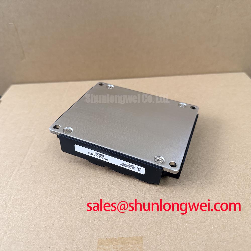
Cooling inspection is part of the electrical diagnosis. Check that the heatsink contact surface is clean, the cooling fins and air path are unobstructed, and the thermal interface material has not hardened, separated, or been displaced. Confirm that the fan, ducting, and enclosure ventilation behave as intended under the real ambient condition. ⚠️ Maintenance Note: Monitor temperature rise at the module and verify the cooling airflow during scheduled service instead of relying only on the inverter fault history.
If the original drive uses a rectifier or front end module, its voltage and current behavior should be reviewed together with the inverter stage. The related SKIIP37AC12T4V1 may be evaluated as an external topology reference, but it is not a stated substitute for the PM75CVA120. Any replacement decision must be based on terminal compatibility, electrical ratings, protection functions, mechanical fit, and the manufacturer’s documentation.
Assembly Integrity and Layout Architecture: Managing Gate Impedance Around PM75CVA120
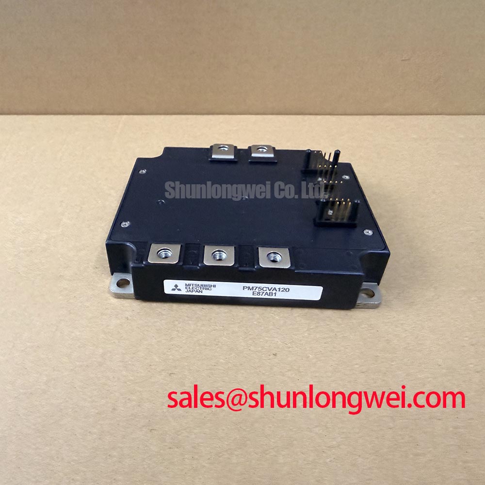
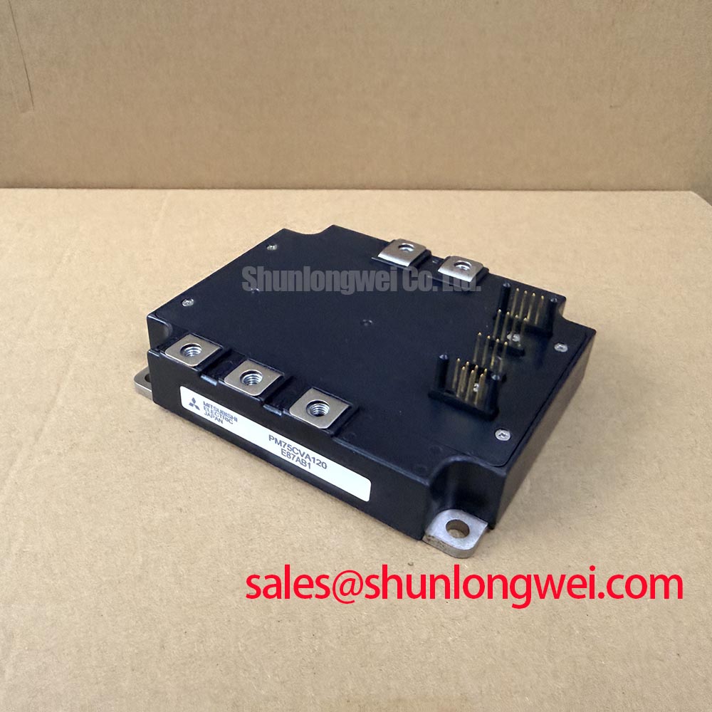
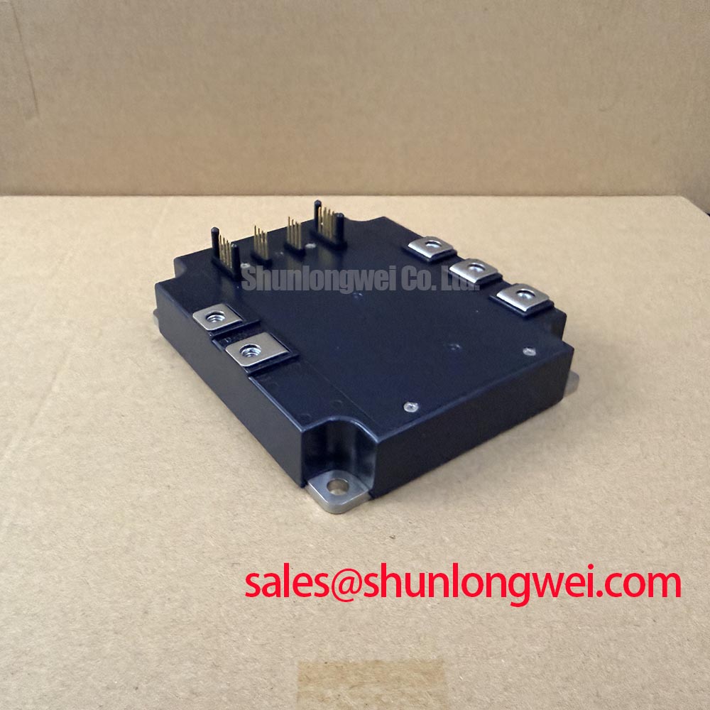
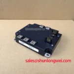
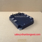
After electrical checks, inspect the mounting surface and terminal assembly. The IPM package must sit evenly against the intended thermal interface, with no foreign material, uneven pressure, or distorted fixing hardware. The supplied factory data identifies the enclosure as a Mitsubishi IPM Module but does not provide a mounting torque, baseplate flatness limit, thermal resistance, or recommended compound thickness. These installation values must be taken from the relevant mechanical drawing or the original equipment service documentation.
Dynamic gate impedance is a system design topic, not an official PM75CVA120 rating in the data supplied here. A gate resistor, ferrite element, active clamp, or negative gate bias may be present in a particular drive, but the correct arrangement depends on the control board, isolation method, switching speed, parasitic inductance, and protection timing. Designers should verify the permitted gate voltage range and gate drive sequence from the device documentation before applying any positive or negative bias.
High dv/dt switching can couple energy into an inactive gate circuit when the layout allows a large common area or when the return path is shared with a high current conductor. To investigate possible cross conduction, observe both complementary gate signals at the module terminals, not only at the driver output. Check dead time, driver supply stability, propagation delay, desaturation or overcurrent response, and the physical condition of the gate loop. A disturbance on one channel may also originate in the isolated driver supply, control timing, or measurement setup.
Mechanical reliability deserves the same attention as the gate circuit. Recheck terminal clamping after the equipment has completed its initial thermal cycle, following the original service specification. Look for discoloration, looseness, oxide contamination, cable strain, and signs that vibration has transferred force into the module terminals. In cold or humid installations, inspect for condensation before energization and allow the enclosure environment to stabilize according to the equipment maintenance procedure.
Where an alternative device is being assessed, the CM100DY-12E can be reviewed as a separate Mitsubishi module reference. It should not be treated as a direct replacement solely because the package family or current class appears similar. Engineers should compare voltage rating, current conditions, internal functions, pin assignment, gate requirements, thermal path, protection behavior, and mechanical dimensions before approving any change.
PM75CVA120 Circuit Protection and Reliability: Controlling Turn Off Overshoot
Turn off protection should be verified with the actual DC link, bus structure, load current, switching speed, and measurement bandwidth used by the drive. The familiar relationship between peak switch voltage, DC link voltage, stray inductance, and current change rate explains why a compact commutation path is valuable, but it is not a replacement for measured data. Minimize the high current loop area and use a symmetrical bus arrangement where the equipment architecture permits, then verify the resulting peak voltage with a properly rated probe during controlled switching tests.
The supplied factory information does not specify a permitted peak overshoot, stray inductance limit, snubber capacitor value, clamp voltage, or short circuit withstand time for this product. Those values must not be inferred from the 1200.0 V rating. A system engineer should select the snubber, clamp, and bus structure only after reviewing the full Mitsubishi switching and protection data, the DC link operating range, and the load commutation profile.
When a turn off waveform exceeds the design margin, inspect the complete path from the module power terminals through the busbar, capacitor bank, current sensor, and return conductor. Check for loose laminated bus connections, excessive conductor separation, damaged capacitors, probe ground lead effects, and an unexpected change in load current. Compare measurements at more than one physical point so that a local ringing artifact is not mistaken for the voltage seen by the semiconductor.
Protection coordination should include gate drive shutdown, overcurrent detection, DC link monitoring, braking or regenerative energy management, and fault recording. The response sequence is determined by the inverter control architecture. Validate it under controlled conditions with the equipment isolated from unnecessary mechanical hazards, and confirm that a protective action does not create a second transient through an uncontrolled commutation path.
For broader application context, engineers may consult the Industrial Applications reference. It should be used as general engineering background rather than as a product specific qualification document. The PM75CVA120 remains an evaluation candidate for heavy duty variable frequency AC motor drive repair only after its documented ratings, terminal arrangement, thermal path, protection requirements, and measured switching behavior have been matched to the target equipment.