Content last revised on September 27, 2026
PS12046 Product Identification and Preliminary Checks
With the DC link isolated and discharged, compare the PS12046 marking, terminal arrangement, and board connections with the equipment documentation before taking cold-state measurements. Record the measurement polarity and connected circuitry, because surrounding capacitors, protection devices, and driver components can affect resistance readings. A comparison with a known-good assembly is more useful than applying an undocumented pass or fail threshold.
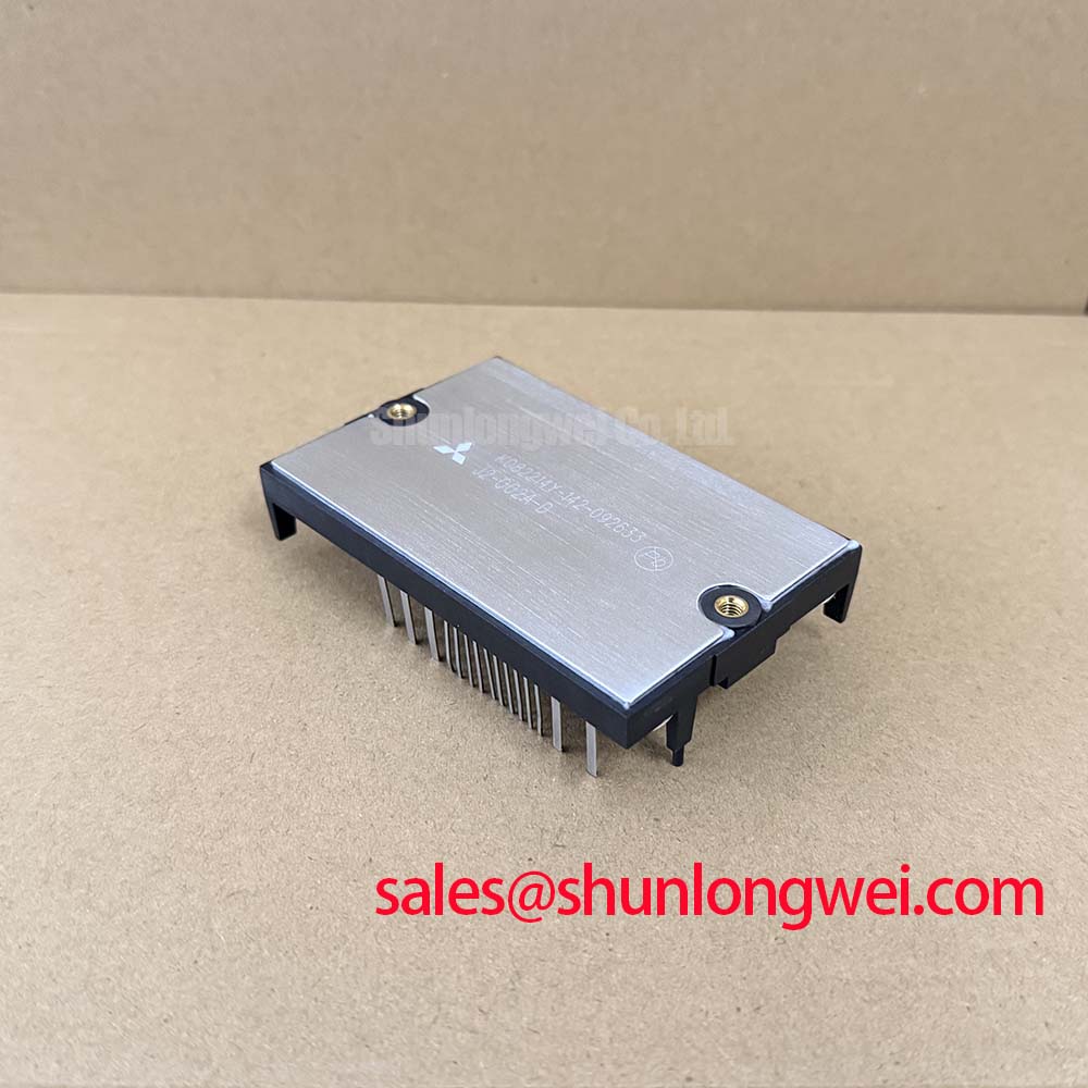
The Mitsubishi Electric PS12046 is identified here as a DIPIPM intelligent power module, with the supplied package description DIP-IPM / Mini DIPIPM. Its voltage and current descriptions do not establish numerical electrical ratings. Replacement approval therefore requires the manufacturer’s model-specific documentation, rather than interpreting “Standard Industrial Rating” or “Standard Operating Current” as usable design limits.
| Product characteristic | Identification or verification requirement |
|---|---|
| Model | PS12046 |
| Manufacturer | Mitsubishi Electric |
| Product category | DIPIPM intelligent power module |
| Supplied package description | DIP-IPM / Mini DIPIPM; confirm the model-specific mechanical drawing |
| Voltage and current ratings | Numerical official specifications must be verified before energization |
| Integration requirements | Confirm terminal assignments, control supply requirements, protection behavior, and thermal limits |
Benchtop Waveform Tuning: Assessing Switching Stress and Gate-Drive Constraints on PS12046
Start waveform evaluation by establishing which signals are accessible at the module terminals. An intelligent power module must not be treated as a bare IGBT with externally accessible gates. Before changing gate impedance, confirm whether the PS12046 documentation permits external adjustment and identifies a corresponding connection. Applying a discrete-device gate-drive technique to a control input can invalidate the test and exceed that input’s permitted electrical conditions.
Design Consideration: switching transitions can couple displacement current through device capacitances and disturb a gate-drive circuit. Low-impedance turn-off paths, active Miller clamps, and negative gate bias are techniques used in suitable gate-driver architectures, but they are not established PS12046 features or approved modifications here. Their relevance depends on the actual internal driver arrangement. For this module, prioritize documented input interfacing, control-supply decoupling, and the relationship between signal reference and power return.
During controlled bench testing, observe control commands, supply stability, fault indications, and phase-node behavior together. Use measurement equipment with appropriate voltage, isolation, and bandwidth capabilities. A narrow disturbance on a displayed waveform may come from probe pickup rather than the circuit; changing the measurement arrangement and comparing correlated channels helps distinguish the two. An unexpected current pulse also warrants examination of command overlap, recovery behavior, and supply disturbance rather than immediate attribution to Miller-induced turn-on.
Engineering Recommendation: keep external control paths compact and separate them from high-current commutation paths where the board architecture allows. Verify creepage and clearance against the equipment’s working voltage, insulation requirements, and environmental conditions. Do not derive those distances from the package name. The permissible layout and any input filtering should follow the module documentation and the system’s required timing behavior.
When assessing replacement options, compare function before comparing headline ratings. The CM100DY-12E is a separate power-module candidate requiring its own topology, driver, terminal, and mechanical assessment; it is not an established direct replacement for PS12046. An apparent similarity in electrical capacity does not demonstrate compatibility with an intelligent power module’s control and protection interfaces.
Transient Dynamics & Electrical Design: Optocouplers vs Coreless-Transformer Digital Isolators in PS12046 Systems
The choice between an optocoupler and a digital isolator belongs to the surrounding control architecture, not to an assumed internal feature of PS12046. Trace the existing schematic to identify where isolation is provided, which reference each signal uses, and whether the interface carries switching commands, fault feedback, or both. Replacing an isolation component requires examination of propagation delay, pulse-width distortion, startup state, and behavior during loss of either supply.
Design Consideration: common-mode transient immunity describes an isolator’s ability to preserve intended signal behavior during rapid changes in potential between its reference domains. Select the required capability from measured system transients and the isolator manufacturer’s stated test conditions. Neither an isolation test voltage nor a CMTI value can be assigned to PS12046 from its product category. Reinforced insulation likewise requires component and equipment documentation appropriate to the intended application.
For a practical comparison, capture the command before and after the isolation barrier while observing the switching node. Check whether a suspected extra pulse is repeatable and whether it coincides with reference movement or a local supply disturbance. Compare turn-on and turn-off timing across channels under relevant operating conditions. This approach separates interface behavior from power-stage behavior without assuming that one isolation technology is inherently suitable for every installation.
DC-link ripple and input-stage control must also be assessed at their actual circuit locations. Phase-angle conduction control is relevant only where the equipment includes that function; it should not be presumed to describe the PS12046 switching method. If bus ripple correlates with protection events, inspect the rectification or supply stage, capacitor condition, and bus connections before modifying command timing.
An RC snubber can influence transient amplitude and damping, but its component values depend on the measured ringing, switching losses, placement, and operating envelope. Engineering Recommendation: evaluate the existing network and its thermal loading before changing it. Any modification should be validated against the module’s confirmed electrical limits and the equipment’s switching behavior, rather than selected from a generic rule.
PS12046 Circuit Protection & Reliability: Evaluating DC-Bus Low-Inductance Laminated Busbar Design
Inspect the commutation path from the local DC-link capacitor through the power stage and back to the capacitor. Long conductors, separated outgoing and return paths, or poorly located connections can increase parasitic inductance. Design Consideration: reducing the enclosed current-loop area can limit inductive turn-off overshoot, but a laminated busbar is a system-level construction choice, not a confirmed PS12046 package feature or installation requirement.
The relevant Engineering Calculation is that peak switch voltage includes the DC-link voltage plus an inductive contribution proportional to loop inductance and current slew rate. That relationship explains why nominal bus voltage alone cannot establish adequate voltage margin. Actual waveforms also contain ringing and measurement effects, so the calculation should support, rather than replace, switching tests against the verified device rating.
Practical design tip: evaluate closely coupled outgoing and return bus paths to reduce commutation-loop area, then verify turn-off voltage margin with appropriately controlled switching tests.
Protection networks require coordinated assessment. An MOV’s voltage-current characteristic, pulse capability, temperature dependence, and location determine whether it can absorb the relevant disturbance. It should not automatically be credited with suppressing a fast local switching spike. Snubber capacitors, bus capacitors, and voltage-clamping devices address different aspects of the transient response; their interaction needs measurement under the equipment’s intended operating conditions.
Thermal evaluation should distinguish average heating from short-duration junction-temperature excursions. If the manufacturer supplies a transient thermal-impedance curve or network, use it within its stated boundary conditions and combine it with a defensible loss estimate. A case-temperature reading alone does not establish peak junction temperature. Confirm mounting flatness, interface condition, and assembly requirements from the mechanical documentation instead of applying an assumed fastening torque or thermal-interface thickness.
For continued operation, retain comparable records of temperatures, switching waveforms, and protection events. The The Ultimate IGBT Knowledge Base provides background for interpreting semiconductor behavior, but model-specific acceptance limits must come from the PS12046 documentation. Parallel operation should not be justified by an assumed positive temperature coefficient: static sharing, dynamic sharing, and driver compatibility require explicit assessment.
Insulation questions also need their own evidence. The mechanism discussed in Partial Discharge is useful background, not proof of this module’s insulation performance or certification. Design Consideration: environmental derating and radiation-related reliability assessments require applicable manufacturer guidance or qualified testing; generic explanations cannot establish an altitude limit, service life, or failure rate for PS12046.
Field Diagnostics & Commissioning: High-Frequency Common-Mode Bearing Current in PS12046 Topologies
When a motor-drive assembly exhibits ringing, intermittent trips, or suspected bearing-current problems, document the cable routing, protective-earth connections, motor configuration, and operating state before replacing the power module. These observations help distinguish a power-stage fault from an installation-dependent disturbance. A successful cold-state check does not exclude a problem that appears only during switching or under load.
Design Consideration: fast switching edges interacting with motor-cable impedance can produce reflected-wave stress at the motor terminals. The resulting peak depends on cable characteristics, termination, edge speed, and losses; no fixed voltage multiplier is established for a PS12046 installation. Measure at the relevant locations with suitable equipment, and compare motor-terminal behavior with inverter-terminal behavior before attributing the disturbance to the module.
Common-mode current follows paths involving cable capacitance, motor structure, grounding, and the drive assembly. Suspected bearing-current activity calls for examination of those paths and appropriate shaft or current measurements. It should not be diagnosed solely from an inverter waveform or an audible motor symptom. Changing a grounding connection may alter several current paths, so record the configuration and assess the result against the equipment’s safety requirements.
Output filters and common-mode chokes should be evaluated against the actual motor, cable, switching pattern, and drive-control requirements. Engineering Recommendation: consult the equipment manufacturer’s filter guidance and verify electrical and thermal loading before installation. Filtering can change voltage drop, resonance, and protection behavior; it is not an unconditional remedy for every transient symptom.
For electric material-handling equipment or forklift traction-controller assessment, first establish whether the PS12046 matches the original circuit’s bus range, current demand, topology, and control interface. The supplied information does not establish low-voltage traction suitability. Procurement should therefore follow identification of the installed part and confirmation of its documented ratings, rather than an application label alone.
After repairing the verified fault, commission the assembly using the equipment’s approved procedure. Confirm stable control supplies, correct command sequencing, expected fault response, and repeatable phase behavior before progressing through the permitted load conditions. If an anomaly remains, preserve its waveform and operating context, then return to the relevant circuit path instead of repeatedly changing module or filter components without a testable explanation.