


Content last revised on May 14, 2026
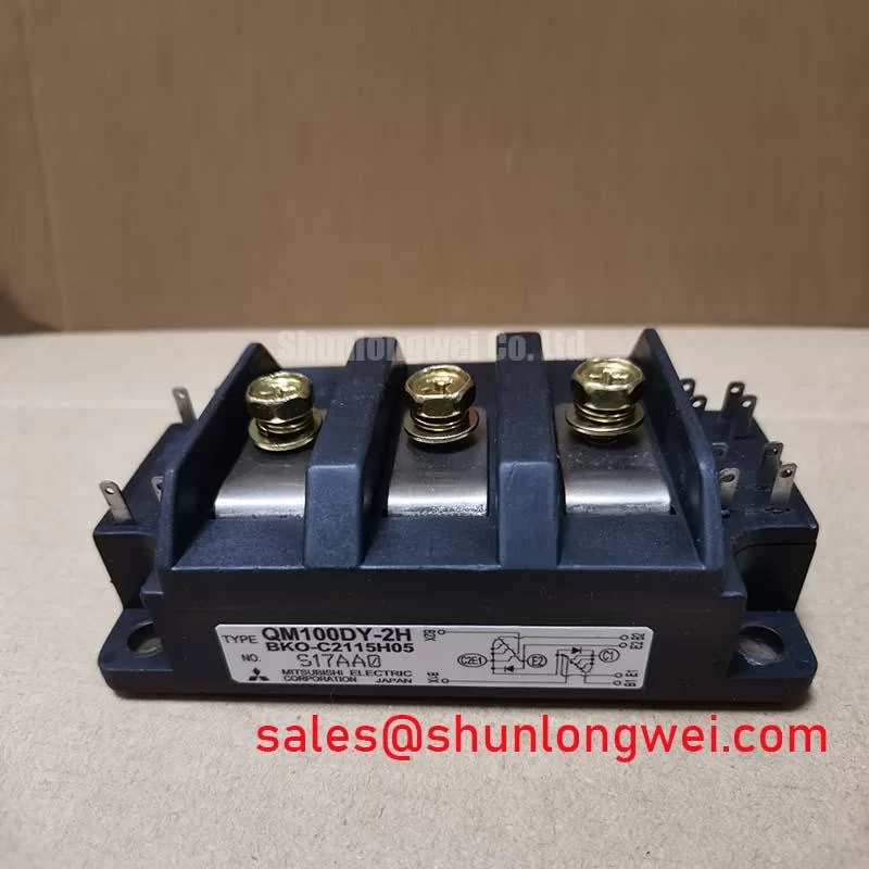
QM100DY-2H | 1200V 100A Dual IGBT Module for High-Reliability Industrial Inverters
Product Overview: Engineering for Thermal Stability and Power Density
The QM100DY-2H is a 1200V/100A dual IGBT module engineered for robust thermal performance, enabling high-reliability power conversion in demanding industrial drive and inverter applications. This module integrates two IGBTs in a half-bridge configuration, offering key specifications of 1200V VCES | 100A Ic | 2.5V VCE(sat). Core engineering benefits include simplified inverter leg design and enhanced system longevity through effective thermal management. The module directly addresses the need for a durable and efficient switching component in high-power systems. Best fit for mid-power industrial motor drives up to 50kW requiring a robust thermal design and simplified inverter leg assembly.
Application Scenarios & Value
System-Level Benefits in AC Motor Drives and Power Conversion Systems
The QM100DY-2H is purpose-built for three-phase power conversion systems, where reliability and efficiency are paramount. Its primary application is in the inverter stage of Variable Frequency Drives (VFDs) and servo drives, controlling AC induction or permanent magnet motors. In a typical VFD operating on a 480V industrial line, the 1200V collector-emitter voltage (VCES) rating provides a crucial safety margin against transient voltage spikes, a common challenge in industrial environments. What is the primary benefit of its dual configuration? It simplifies the mechanical layout of an inverter phase leg, reducing busbar complexity and ensuring the high-side and low-side switches are thermally and electrically matched. This inherent pairing is critical for minimizing switching imbalances and improving the long-term reliability of the entire drive system. For applications requiring higher current handling within a similar architecture, the CM200DY-24H provides a 200A capability. For a step up to 150A, engineers might also evaluate the QM150DY-H.
Key Parameter Overview
Decoding the Specs for Thermal Performance and Efficiency
The technical specifications of the QM100DY-2H are foundational to its performance in high-stress applications. The values below, extracted from the official datasheet, highlight the module's capacity for efficient power handling and thermal robustness. Understanding these parameters is key to optimizing system design for both performance and reliability.
| Parameter | Symbol | Value | Conditions |
|---|---|---|---|
| Collector-Emitter Voltage | VCES | 1200V | VGE = 0V |
| Gate-Emitter Voltage | VGES | ±20V | |
| Collector Current (DC) | IC | 100A | TC = 25°C |
| Collector Current (Pulse) | ICP | 200A | |
| Collector-Emitter Saturation Voltage | VCE(sat) | 2.5V (Typ) / 3.2V (Max) | IC = 100A, VGE = 15V |
| Power Dissipation | PC | 625W | Per Transistor |
| Thermal Resistance (Junction to Case, IGBT) | Rth(j-c) | 0.20 °C/W | Per Transistor |
| Operating Junction Temperature | Tj | -40 to +150 °C |
Download the QM100DY-2H datasheet for detailed specifications and performance curves.
Technical Deep Dive
The Engineering Impact of Thermal Resistance on System Longevity
While electrical ratings like voltage and current define a module's power handling capacity, its thermal characteristics often dictate its real-world reliability. A critical parameter in the QM100DY-2H datasheet is the junction-to-case thermal resistance, Rth(j-c), specified at 0.20 °C/W for the IGBT. What is a key benefit of its thermal design? Efficient heat dissipation for enhanced system reliability. This value quantifies how effectively heat generated during switching and conduction can be moved from the active silicon die to the module's baseplate.
Think of thermal resistance as the narrowness of a pipe. A lower Rth(j-c) value is like a wider pipe, allowing heat (the 'water') to flow away from the delicate semiconductor junction far more easily. This efficiency directly impacts the design of the cooling system. A lower thermal resistance means that for a given power loss, the junction temperature will be lower, or conversely, the module can handle more power for a given maximum junction temperature. This provides engineers with valuable design flexibility: they can either reduce the size and cost of the required heatsink, or push for higher power density without compromising the component's lifespan, which is a key consideration in modern thermal management strategies.
Frequently Asked Questions (FAQ)
What is the main advantage of the dual-switch (half-bridge) configuration in the QM100DY-2H?
The primary advantage is design simplification and enhanced reliability. By packaging a matched pair of IGBTs for a single inverter phase leg, it reduces component count, simplifies the PCB and busbar layout, and ensures symmetrical thermal and electrical performance between the high and low-side switches. This is crucial for preventing switching imbalances that can lead to increased losses and premature failure in a Pulse Width Modulation (PWM) scheme.
How does the 1200V VCES rating of the QM100DY-2H benefit designs for 480V AC systems?
A 480V AC line can have a rectified DC bus voltage of approximately 678V (480V * √2). The 1200V rating provides a substantial safety margin above this operating voltage. This headroom is essential to withstand voltage overshoots caused by stray inductance during fast switching events, protecting the module from catastrophic failure and ensuring robust operation in electrically noisy industrial environments.
What is the significance of the thermal resistance Rth(j-c) value for system design?
The Rth(j-c) of 0.20 °C/W is a direct measure of the module's ability to transfer heat from the silicon chip to its baseplate. A lower value, like that of the QM100DY-2H, allows for a cooler junction temperature under load. This directly translates to improved system reliability, as high temperatures accelerate aging. It also enables engineers to design more compact systems by using smaller heatsinks or to increase the power output without exceeding the maximum junction temperature of 150°C.
Is a negative gate voltage recommended for turning off the QM100DY-2H?
Yes, the datasheet specifies characteristics with a gate-emitter voltage (VGE) of +15V for turn-on and -10V for turn-off. Using a negative gate voltage provides a more robust and definitive turn-off state. It increases noise immunity by holding the gate firmly below its threshold voltage, preventing unintended turn-on caused by Miller capacitance (Cgc) during the rapid voltage rise (dv/dt) on the opposing switch in the half-bridge.
Strategic Outlook
The QM100DY-2H represents a proven and reliable building block for industrial power electronics. Its balanced specifications—combining robust 1200V/100A ratings with a thermally efficient package—make it a durable choice for designers creating next-generation motor drives, power supplies, and welding equipment. As industrial systems continue to demand higher power density and greater operational longevity, the design principles embodied in this Mitsubishi module remain fundamentally relevant. For engineers looking to extract maximum performance from their designs, a thorough understanding of its thermal characteristics is not just a recommendation, but a prerequisite for success, a topic often explored when decoding IGBT datasheets.