Content last revised on February 9, 2026
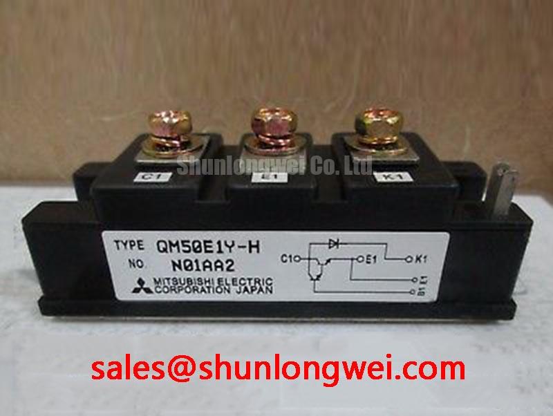
QM50E1Y-H: An Engineer's Perspective on this Robust 600V Dual IGBT Module
Introduction to the QM50E1Y-H
A Pragmatic Choice for Reliable Industrial Power Conversion
The Mitsubishi QM50E1Y-H is a dual IGBT module designed for dependable performance in mainstream industrial applications. It offers a robust specification of 600V | 50A and a high isolation voltage of 2500V, establishing a strong foundation for building cost-effective and reliable power stages. Key engineering benefits include simplified thermal design due to its insulated package and predictable performance under load. This module directly addresses the challenge of achieving reliable power control without incurring excessive system costs, making it a workhorse for general-purpose inverters and power supplies. For industrial systems requiring dependable switching in a standard half-bridge layout, the QM50E1Y-H offers a compelling balance of performance and practical design advantages.
Key Parameter Overview
Decoding the Specs for Enhanced Thermal Reliability
The technical specifications of the QM50E1Y-H underscore its suitability for medium-power switching applications where reliability and thermal performance are critical. The parameters are organized below to provide a clear view of the module's capabilities, from its operational limits to its switching characteristics.
| Absolute Maximum Ratings (Tj = 25°C) | |
|---|---|
| Collector-Emitter Voltage (VCES) | 600V |
| Collector Current (IC) | 50A |
| Collector Power Dissipation (PC) | 170W |
| Junction Temperature (Tj) | -40 to +150°C |
| Isolation Voltage (Viso) | 2500V (AC, 1 minute) |
| Electrical Characteristics - IGBT (Tj = 25°C) | |
| Collector-Emitter Saturation Voltage (VCE(sat)) | 2.7V (Max) at IC = 50A |
| Thermal Resistance (Rth(j-c)) - IGBT | 0.5 °C/W (Max) |
| Turn-On Time (ton) | 1.0 µs (Typ) |
| Turn-Off Time (toff) | 2.0 µs (Typ) |
| Electrical Characteristics - Diode (Tj = 25°C) | |
| Forward Voltage (VF) | 2.5V (Max) at IF = 50A |
| Reverse Recovery Time (trr) | 0.4 µs (Typ) |
| Thermal Resistance (Rth(j-c)) - Diode | 0.8 °C/W (Max) |
Download the QM50E1Y-H datasheet for detailed specifications and performance curves.
Application Scenarios & Value
Achieving System-Level Benefits in Industrial Inverters
For design engineers developing small to medium-sized power systems, the QM50E1Y-H provides a straightforward path to a robust and thermally manageable solution. Its feature set is particularly well-suited for applications like a Variable Frequency Drive (VFD) rated for motors up to 15 kW, commercial welding equipment, and Uninterruptible Power Supplies (UPS).
What is the primary benefit of its insulated design? Enhanced long-term reliability by simplifying the thermal interface. The module's key advantage is its 2500V isolation voltage. This allows engineers to mount the module directly onto a grounded heatsink without the need for additional, thermally resistive insulating pads. This approach not only reduces assembly time and cost but also improves the thermal pathway from the IGBT junction to the heatsink, leading to lower operating temperatures and enhanced system reliability. The dual configuration further simplifies the layout of a standard half-bridge, a topology central to most inverters. While the QM50E1Y-H is optimized for this power class, for applications demanding higher current handling, the related QM100DY-H offers a 100A rating within a similar package family. Correctly decoding IGBT datasheets reveals how this integrated isolation feature directly translates to a more reliable and cost-effective end product.
Technical Deep Dive
Implications of the Insulated Package on Thermal Design
A crucial aspect of power electronic design is effective thermal management. The QM50E1Y-H integrates a key feature to aid in this: its electrically isolated baseplate. The Viso rating of 2500V is not just a safety metric; it's a design-enabling feature. Think of the standard, non-isolated module as a bare hot plate that requires a separate, fragile ceramic coaster (insulating pad) before you can place it on a wooden table (the heatsink). That coaster adds a layer that slows down heat transfer.
The QM50E1Y-H, with its insulated design, is like a hot plate with a built-in, high-performance insulating base. You can bolt it directly to the table. This direct mounting, combined with a thermal resistance (Rth(j-c)) of 0.5 °C/W, creates a predictable and efficient path for waste heat to exit the semiconductor. This predictability is vital for engineers during the heatsink selection phase, allowing for more accurate thermal simulations and potentially enabling the use of a smaller, more cost-effective heatsink while maintaining safe operating temperatures. This synergy between isolation and thermal resistance is a cornerstone of the module's value proposition for industrial applications where long-term reliability is non-negotiable.
Frequently Asked Questions (FAQ)
How does the dual IGBT configuration of the QM50E1Y-H benefit a power circuit design?
The dual, or half-bridge, configuration integrates two IGBTs and two freewheeling diodes in a single package. This is the fundamental building block for the leg of a three-phase inverter or a chopper circuit. Using a single module instead of multiple discrete components simplifies the PCB layout, reduces stray inductance between switches, and streamlines the manufacturing assembly process.
What is the practical impact of a VCE(sat) of 2.7V on system efficiency?
The Collector-Emitter Saturation Voltage, or VCE(sat), represents the voltage drop across the IGBT when it is fully turned on. This voltage drop, multiplied by the current flowing through it, determines the conduction power loss. A VCE(sat) of 2.7V at 50A means that during conduction, the switch dissipates approximately 135W of power as heat. While not the lowest in its class, this is a solid, predictable value that allows for straightforward thermal design and ensures that conduction losses are managed effectively in applications like a Variable Frequency Drive (VFD) operating at lower to moderate switching frequencies.
How does the junction-to-case thermal resistance (Rth(j-c)) of 0.5 °C/W influence heatsink selection?
The Rth(j-c) value quantifies how effectively heat can travel from the internal silicon chip (junction) to the module's metal baseplate (case). A lower value is better. A value of 0.5 °C/W means that for every watt of power dissipated as heat, the junction temperature will rise only 0.5°C above the case temperature. This low thermal resistance gives the designer more thermal budget to work with, potentially allowing for a smaller heatsink or enabling operation at higher ambient temperatures without exceeding the maximum junction temperature of 150°C.
For engineers and procurement managers looking to specify a reliable power component, the QM50E1Y-H from Mitsubishi offers a proven and practical solution. To further discuss how this module fits into your specific design requirements, please reach out to our technical sales team for a detailed consultation.

