

Content last revised on October 16, 2026
Preventing Spurious Faults: Insulation Resistance and Terminal-to-Baseplate Withstand Testing for QM50TX-HB
Disconnect the power stage, verify that the DC link is discharged, and separate external wiring before investigating leakage between the QM50TX-HB terminals and its mounting base. Record whether the fault appeared during startup, sustained loading, or a change in cabinet temperature; those conditions help distinguish an insulation concern from contamination, cooling deterioration, or a problem elsewhere in the assembly.
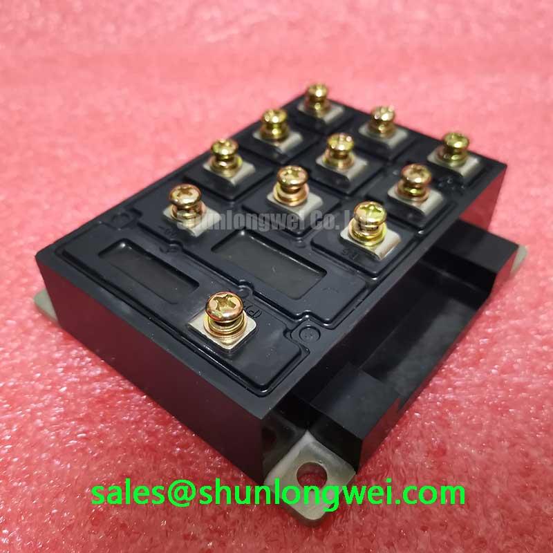
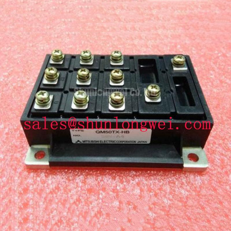
The Mitsubishi Electric QM50TX-HB is a 600 V, 50 A Isolated Darlington Module. These ratings are subject to the applicable datasheet conditions. Its Darlington classification matters during repair: the control interface requires evaluation as a bipolar transistor drive, including base current and stored-charge removal. An IGBT gate-drive procedure cannot be transferred directly to this device.
Isolate the module from driver electronics, suppression networks, and external conductors before connecting an insulation tester. As a Design Consideration, attached circuits can introduce parallel leakage paths or receive test stress that was intended only for the power module. Identify the intended terminal grouping and baseplate connection from the approved test procedure before applying voltage.
Insulation resistance measurement and dielectric withstand testing answer different questions. A resistance measurement evaluates leakage under specified conditions; a withstand test applies a defined electrical stress with its own acceptance criteria. The 600 V device rating must not be interpreted as a terminal-to-baseplate test voltage. Use the module-specific insulation procedure to establish the test voltage, duration, terminal connections, and acceptance limit.
A useful maintenance record includes the disconnected wiring configuration, instrument identification, ambient conditions, surface condition, and measurement stability. As an Engineering Recommendation, compare results obtained under equivalent conditions rather than treating readings taken in different humidity conditions as directly interchangeable. Discharge the tested assembly through the instrument’s prescribed procedure before restoring connections.
Inspect accessible insulating surfaces for conductive dust, coolant residue, and moisture tracks. Cleaning should follow the equipment maintenance procedure and preserve terminal markings and insulating surfaces. A change after cleaning can help locate a surface leakage contribution, but a terminal-to-baseplate measurement alone cannot identify the condition or material of an internal substrate.
The distinction between surface leakage and bulk breakdown is explained by the physical principles of Dielectric Strength and High-Voltage Breakdown Testing. As a Design Consideration, creepage and clearance also depend on the surrounding assembly: terminal hardware, cable lugs, contamination, and nearby grounded metal all affect the installed insulation path. Check the actual assembly against its approved mechanical arrangement.
After a cold shutdown or a rapid environmental change, inspect the enclosure for condensation before energization. Where contamination repeatedly returns, examine cabinet sealing, airflow, and maintenance practices. These checks address the operating environment without assigning an unsupported humidity rating or insulation lifetime to the module. Keep the observations with the equipment history so later maintenance can distinguish recurring environmental exposure from an isolated service event.
Field Diagnostics & Commissioning: High-Frequency Common-Mode Bearing Current in QM50TX-HB Topologies
Measure switching voltage at the drive output and motor terminals when nuisance trips follow a motor-cable change. As a Design Consideration, cable propagation and impedance mismatch can produce different waveforms at those locations. Use appropriately rated differential probes and a documented connection method; probe arrangement and bandwidth can influence the apparent overshoot.
Common-mode current follows capacitive paths between the power circuit, motor, cable shield, and protective earth. Bearing current is one possible branch of that network. Its presence and significance require measurements of the installed system; audible motor noise or an intermittent drive alarm does not establish bearing discharge as the cause.
Record cable routing, shield termination, motor grounding, and the switching conditions alongside the waveforms. An Engineering Recommendation is to compare these observations with the equipment’s approved installation arrangement before selecting an output filter. Cable length alone does not determine the required filter or choke, and an accessory can change both the terminal waveform and drive loading.
If an output filter is being evaluated, assess its effect on overshoot, common-mode current, heating, and control stability across the intended operating range. Selection belongs to the system design because the relevant conditions include cable construction, motor impedance, switching behavior, and drive control. Keep separate records for motor-terminal voltage stress and bearing-related measurements so that improvement in one is not mistaken for proof about the other.
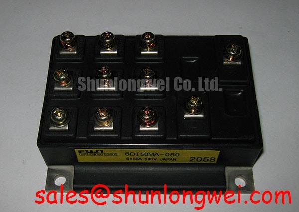
For compatibility assessment, engineers may evaluate the QM50TX-HB in existing high-dynamics multi-axis CNC and robotics servo equipment whose original power-stage requirements match the device. The comparison below separates established QM50TX-HB identity data from the checks needed when considering 6DI50AH-050 as another reference in a sourcing review.
| Selection checkpoint | QM50TX-HB | 6DI50AH-050 comparison requirement |
|---|---|---|
| Manufacturer | Mitsubishi Electric | Consult Datasheet |
| Device category | Isolated Darlington Module | Compare transistor technology and circuit configuration |
| Rated voltage | 600 V — subject to datasheet conditions | Compare voltage definitions and test conditions |
| Rated current | 50 A — subject to datasheet conditions | Compare current conditions and thermal limits |
| Control interface | Evaluate base-drive requirements | Compare terminal functions and drive requirements |
| Mechanical integration | Match the original assembly drawing | Compare footprint, terminal positions, and mounting requirements |
The table supports an engineering comparison rather than establishing interchangeability. Matching headline ratings does not resolve terminal mapping, switching behavior, thermal contact, or protection compatibility. During a replacement review, retain the original wiring diagram and mounting arrangement as controlled references, then document each difference before approving installation.
Power-supply and driver checks should also distinguish the function of each semiconductor stage. A system topology review may include a separate device such as CM400DY-12, but its role must follow the actual circuit diagram. It should not be assigned a rectifier function or treated as a QM50TX-HB replacement from its product name.
Before returning the assembly to operation, examine the fuse holder and its connections for deterioration that could affect fault interruption. As an Engineering Recommendation, review the protection device against the prospective fault conditions and the semiconductor protection documentation. This establishes the inputs for the fault-energy assessment rather than assuming that an unchanged fuse remains suitable after a power-stage modification.
Benchtop Waveform Tuning: Mitigating Stress via Short-Circuit Energy Let-Through Matching on QM50TX-HB
Compare the fuse’s total clearing behavior with the actual fault circuit before approving short-circuit protection. As a Design Consideration, total clearing I²t describes the time integral of current squared through interruption; it is useful for coordination, but it does not independently establish transistor survival. Semiconductor stress also depends on voltage, current distribution, temperature, and the time spent outside the permissible operating area.
Distinguish an overload, an output short circuit, and a DC-link fault in the protection review. Each can present a different current path and interruption requirement. Check the fuse’s applicable voltage rating, breaking capacity, and manufacturer coordination information for the intended circuit. Neither rapid clearing nor a favorable I²t comparison alone demonstrates that the module enclosure will remain intact.
Driver protection requires equal attention because a Darlington transistor can retain stored charge during turn-off. An Engineering Recommendation is to inspect the base-drive waveform together with collector current and collector-emitter voltage. Evaluate forward drive, charge removal, and any reverse base-emitter stress against the applicable device limits and original driver design.
Where the equipment uses collector-emitter voltage monitoring, verify its behavior during normal switching and under the approved protection test. Detection delay and controlled turn-off must balance nuisance immunity against semiconductor stress. Do not infer a short-circuit safe operating area from the 50 A current rating, and do not transfer an IGBT desaturation setting to the Darlington interface without validating the circuit.
Reduce unnecessary loop area in the power and base-drive paths while preserving the approved terminal arrangement. As a Design Consideration, parasitic inductance can contribute to voltage overshoot and oscillation during current transitions. Evaluate damping from measured waveforms and driver behavior; the appropriate components depend on the assembled circuit rather than a universal resistance value.
Inspect the heatsink contact surface, mounting hardware, and thermal interface material whenever the module is removed. Restore the interface using the specified material, application method, tightening sequence, and torque for the assembly. Excess material, trapped contamination, or uneven seating can impair heat transfer. Do not apply pressure-contact, disc-spring, or double-sided cooling procedures unless the equipment construction explicitly calls for them.
Maintenance Note: Trend terminal temperature rise and check heatsink airflow during scheduled service, with the equipment isolated before cleaning or checking connection tightness.
Set inspection intervals from operating conditions, contamination exposure, thermal history, and the equipment maintenance plan. Assess thermal interface condition during authorized disassembly rather than repeatedly disturbing a stable mounting joint. Terminal tightening should use calibrated tools and the applicable assembly specification; indiscriminate retightening can damage a connection or obscure the original cause of heating.
For broader topology context, the Shunlongwei guide Peak Efficiency in Solar and Energy Storage can support discussion of switching paths and system losses. It is a system-level reference, while manufacturer information remains the appropriate basis for device-specific limits; Mitsubishi Electric Power Semiconductors & High-Power Modules provides the manufacturer’s power-device resource context.
During controlled recommissioning, compare driver behavior, terminal voltage, current, and temperature trends with the approved equipment baseline. Retain the waveform captures and protection settings with the service record. If abnormal heating or oscillation persists, investigate the associated connection, cooling path, or driver circuit before extending operation to the intended load.