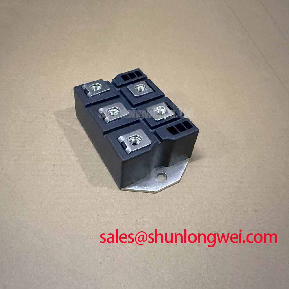
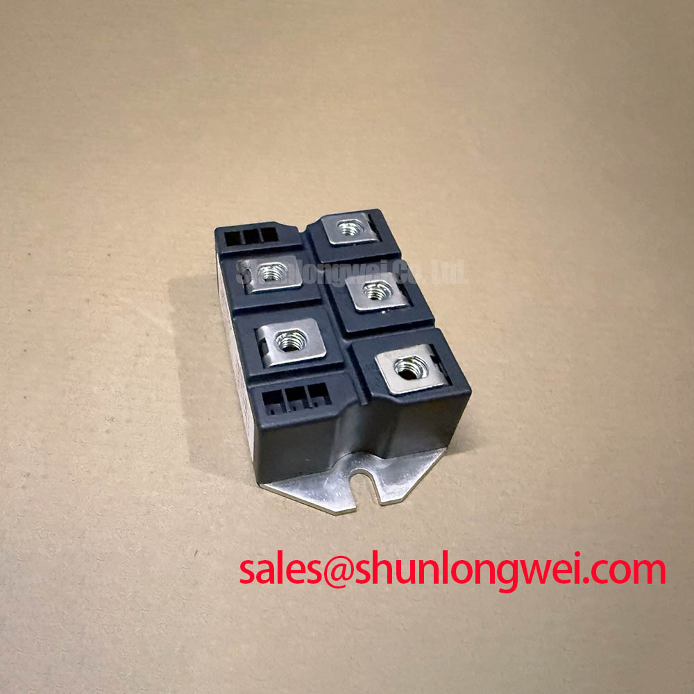





Content last revised on September 27, 2026
S3PDB250N16 Thermal Electrical Optimization and Peak Current Verification
The first selection check is the voltage boundary. The listed inverter collector emitter voltage is VCES 1600 V, while the rectifier diode repetitive peak reverse voltage is also VRRM 1600 V. These are official specification values supplied for the product and should be compared with the maximum blocking voltage that can occur in the intended high voltage three phase motor solid state soft starter.
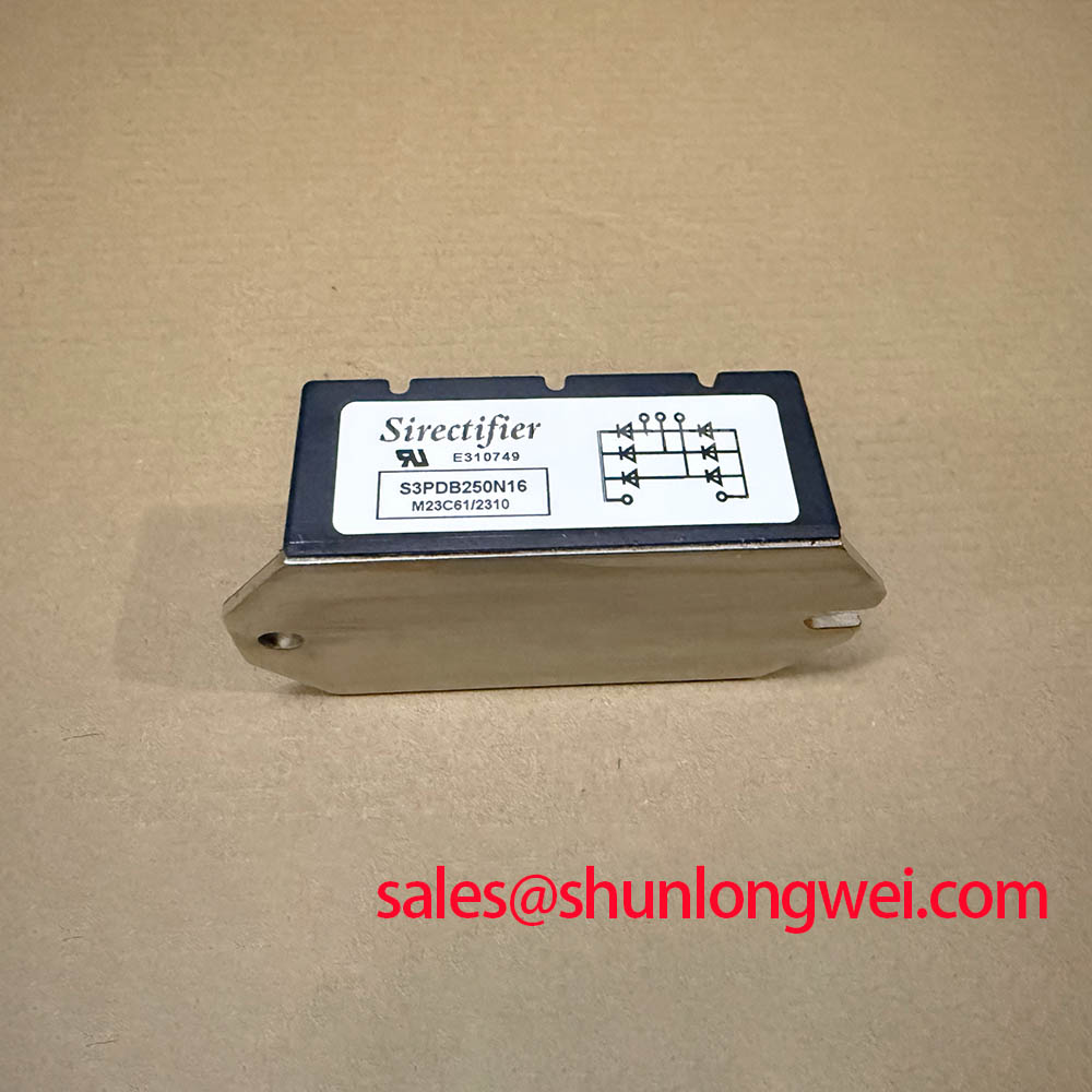
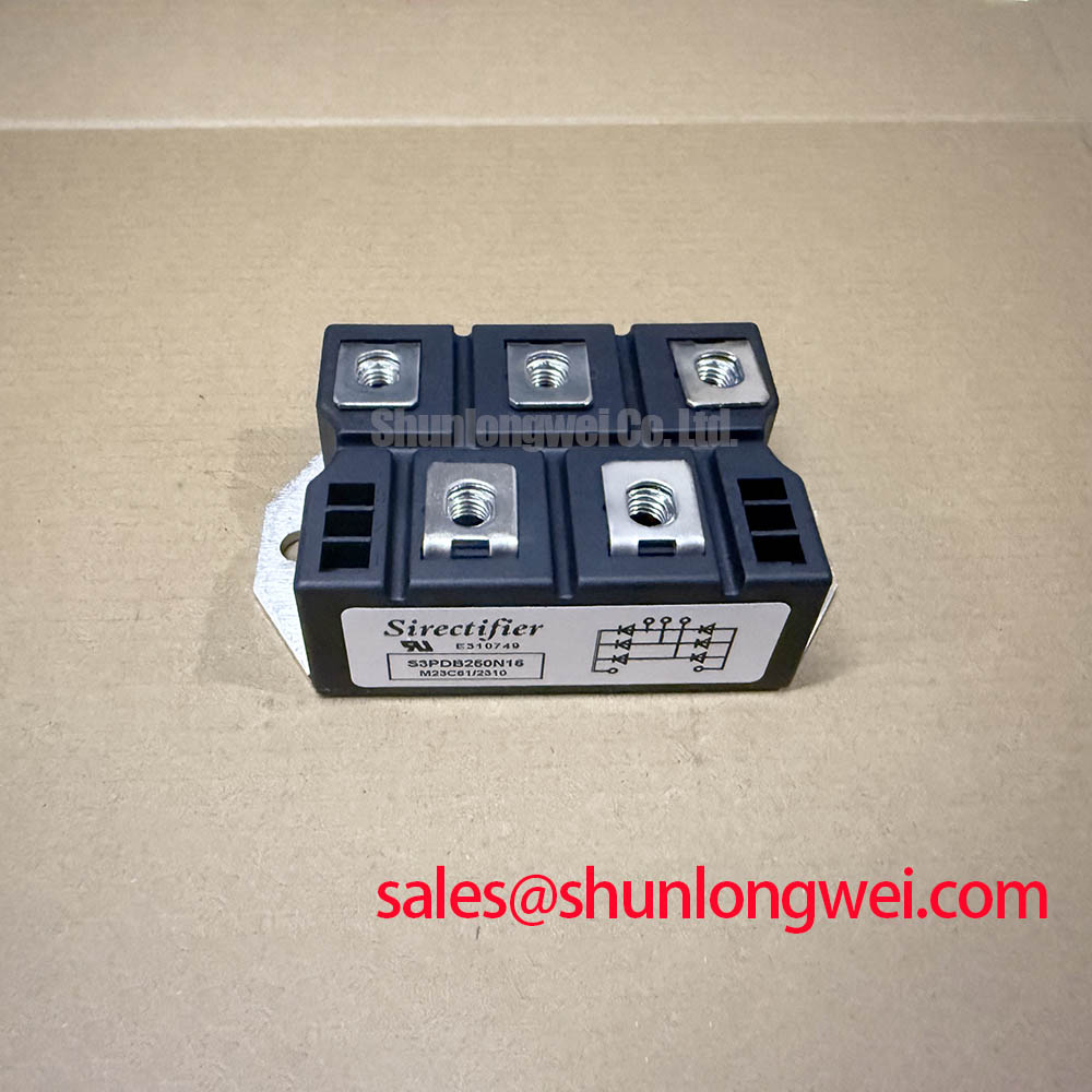
The listed inverter continuous collector current is IC 250 A at TC = 80°C. The corresponding inverter pulsed collector current is ICP 500 A for 1 ms. On the rectifier side, the output current is specified as ID 250 A at TC = 80°C. These ratings should not be treated as unrestricted system operating targets. The system designer must verify semiconductor temperature, load profile, switching or conduction interval, enclosure cooling, and the actual current waveform before approving the operating point.
A sinusoidal soft starter current waveform can create different thermal conditions from a steady direct current test. During each conduction interval, engineers should examine the phase current, conduction angle, starting frequency, motor acceleration time, and repeated start duty. A datasheet value for a short pulse does not by itself establish an allowable repeated surge profile. The relevant factory surge and transient parameters, including any 10 ms half cycle surge rating or fuse coordination data, must be confirmed from the applicable manufacturer documentation before protection settings are finalized.
For a replacement assessment, record the original fuse class, semiconductor fuse rating, clearing characteristics, and measured current waveform. The fuse I²t value must be compared with the module’s published surge and short circuit withstand information rather than inferred from the 250 A continuous rating. If the required fuse coordination table is not available for this exact device, the result should remain an engineering verification item.
The isolation rating is listed as Visol 2500 V AC for 1 minute. This value is an official insulation test specification, not a complete statement of system insulation coordination. Clearance, creepage, pollution level, enclosure construction, cable routing, and transient overvoltage category remain system level matters. The device should be evaluated according to the insulation requirements of the finished starter and the applicable compliance plan.
Field Diagnostics and Off State Voltage Rise in Soft Starter Topologies
During commissioning, inspect the voltage across each phase path with an appropriately rated differential measurement system. Compare the three phase waveforms under the same motor and line conditions. Unequal blocking voltage, unexpected ringing, or a phase dependent turn on event may indicate a layout, snubber, gate control, measurement, or device condition issue. The waveform should be compared with a known good assembly whenever possible.
In a high voltage three phase soft starter, the rate of rise of off state voltage can interact with device capacitance, wiring inductance, control timing, and the impedance of the surrounding network. An RC snubber may be considered when measured ringing or transient voltage exceeds the system design objective, but the resistor and capacitor values must be selected from measured waveforms, loss calculations, voltage ratings, pulse capability, and thermal results. They should not be copied from an unrelated module.
Series reactors or other current shaping elements can also influence commutation and peak current. Their use requires verification of motor starting torque, phase balance, voltage drop, control timing, and fault response. A saturable reactor may behave differently during initial energization, steady conduction, and an abnormal current event, so testing should cover each operating state rather than relying on a single oscilloscope capture.
Terminal connections deserve the same attention as the semiconductor rating. Clean the mating surfaces according to the equipment maintenance procedure, inspect for discoloration or looseness, and confirm that phase conductors are arranged symmetrically. The exact terminal hardware, busbar geometry, tightening torque, and permitted conductor arrangement must come from the mechanical drawing or installation documentation for the module and the finished equipment.
💡 Pro Tip: Disconnect all power sources and verify the discharge state of the starter before touching power terminals or removing control and sensing connections.
For background on voltage rise, commutation, and semiconductor switching behavior, engineers can consult the Thyristor and Silicon Controlled Rectifier dynamics reference. The terminology should still be reconciled with the exact SIRECTIFIER documentation because a general reference does not replace a product specific electrical limit.
S3PDB250N16 Short Circuit Withstand and Fuse Coordination
A dead short in a high voltage motor starter is a protection coordination problem, not a current rating comparison alone. The listed IC 250 A and ID 250 A values describe continuous current conditions at the stated case temperature. They do not define the energy that the module can safely absorb during a fault. The protection study must use the prospective fault current, source impedance, fuse operating curve, clearing time, and the manufacturer’s published semiconductor withstand data.
When reviewing a semiconductor fuse, compare its let through I²t and peak let through current with the exact module data. The comparison must include the real upstream transformer, cable impedance, phase arrangement, and available short circuit current. If a fuse I²t coordination table is absent from the source documentation, the engineer should obtain the required data before treating the protection scheme as validated.
Oscilloscope measurements and event records can help identify whether a fault was cleared consistently across all three phases. Useful observations include current rise, voltage collapse, fuse interruption, gate or control response, and the condition of the module after isolation. A single successful interruption is not field life data and should not be used to claim a guaranteed short circuit capability.
The 1600 V blocking ratings should also be reviewed against the transient created when fault current is interrupted. Busbar arrangement, stray inductance, line reactors, snubbers, and the position of voltage measurement points can materially affect the observed overshoot. Minimize the high current commutation loop and verify the peak voltage during controlled switching and fault interruption tests. The acceptable margin must be determined by the system engineer from the actual DC link or line voltage and the documented device limits.
The IEC 60747 9 reference for IGBTs provides useful standard context for semiconductor device terminology and testing. It does not establish the short circuit withstand value of this particular S3PDB250N16 assembly. Product specific limits remain necessary for a defensible fuse selection.
For a sourcing comparison, the SKD 25/14 may be reviewed as a separate device listing, but voltage, current, topology, mechanical fit, thermal interface, and protection coordination must be checked independently. Similar appearance or a related application does not establish interchangeability.
S3PDB250N16 Junction to Heatsink Heat Dissipation
The continuous current specifications are stated at TC = 80°C, making thermal verification essential for any high current installation. The product information supplied here does not provide a complete thermal resistance table, case drawing, mounting torque, baseplate flatness requirement, or thermal interface material specification. Those details should be obtained from the applicable mechanical and thermal documentation rather than estimated from the current rating.
During installation, verify that the heatsink contact surface is clean, flat within the documented assembly requirement, and free from burrs or particles. Apply the approved thermal interface material consistently and tighten the mounting hardware according to the manufacturer’s specified sequence and torque. Excessive or uneven pressure can distort the package or create nonuniform contact; insufficient pressure can increase thermal impedance. Any required torque value is therefore an installation specification to be confirmed, not a universal value for this model.
Thermal testing should begin with the actual phase current waveform and the intended motor starting cycle. Measure the case or mounting reference temperature at the location defined by the test method, then compare it with the specified operating condition. Check all phase paths separately because unequal busbar resistance, terminal pressure, or current sharing can produce different temperatures even when the control commands are identical.
When the module is used in a high voltage three phase motor solid state soft starter, evaluate repeated starts, stalled acceleration, bypass transition, ambient temperature, fan or airflow condition, and cabinet heat accumulation. The 250 A rating at the stated case temperature does not independently guarantee a particular enclosure duty cycle. Designers should verify the full thermal transient with the finished heatsink and protective control sequence.
The Wide Bandgap Revolution engineering guide offers broader context on power semiconductor design challenges and switching behavior. It should be used as background material only; the S3PDB250N16 evaluation must remain tied to its published 1600 V, 250 A, 500 A pulse, 2500 V isolation, and product specific mechanical data.