

Content last revised on September 23, 2026
SEMIX604GB12E4S Thermal-Electrical Optimization: Dynamic Braking Chopper Operation Practical Tuning
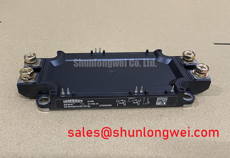
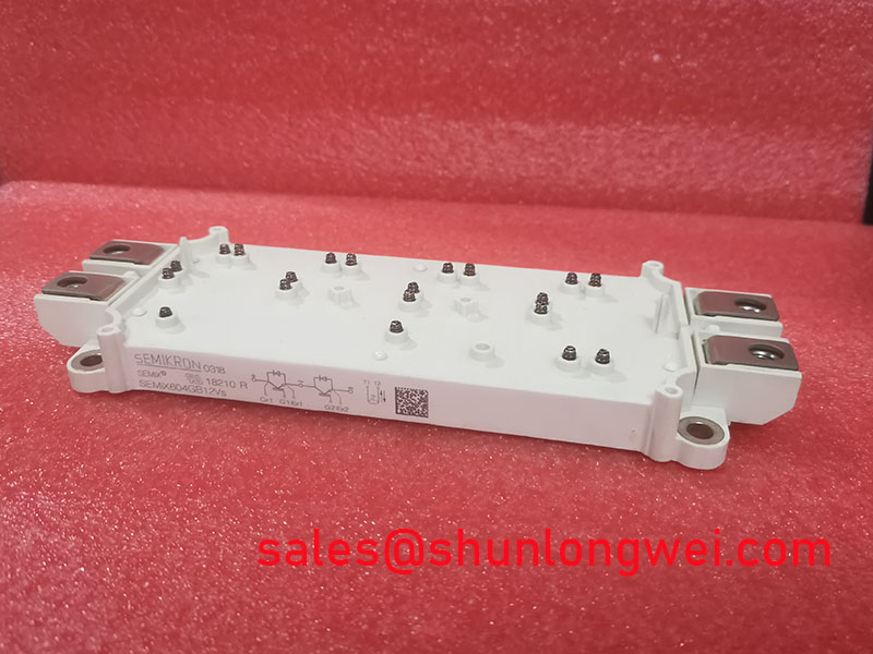
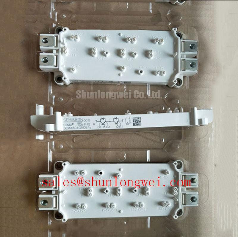
Verify the nameplate, inspect the SEMiX housing for cracks or deformation, and confirm the electrical boundary before removing the existing power module from a variable frequency AC motor drive. The Semikron SEMIX604GB12E4S is specified with a 1200.0 V voltage rating and 600.0 A current rating in the SEMiX Module package. These are official product parameters; switching frequency, gate-drive conditions, thermal limits, overload capability, and protection settings must be confirmed against the applicable manufacturer documentation and the complete drive design.
| Parameter | Official Specification |
|---|---|
| Manufacturer | Semikron |
| Part number | SEMIX604GB12E4S |
| Product category | IGBT Module |
| Voltage rating | 1200.0 V |
| Current rating | 600.0 A |
| Package | SEMiX Module |
For procurement and service teams, the voltage and current ratings identify the replacement class, but they do not by themselves confirm interchangeability. Gate terminal arrangement, diode configuration, mechanical hole pattern, electrical isolation, thermal interface requirements, and the original drive manufacturer’s gate resistance must be checked before installation. The Semikron-Danfoss Power Electronics & Modules Official Hub is a suitable reference point for manufacturer-level product information.
In a heavy-duty variable frequency AC motor drive, a braking chopper diverts regenerative energy from the DC link into a braking resistor when the motor decelerates. The SEMIX604GB12E4S may be evaluated for this switching position when its electrical, gate-drive, cooling, and mechanical requirements match the original design. The resistor and chopper must be assessed as one energy-handling path rather than as independent replacement items. The system engineer should verify the DC-link operating range, pulse energy, duty profile, resistor thermal behavior, and protection sequence during controlled commissioning.
During a service inspection, begin with the DC-link trend recorded during acceleration and deceleration. A rising link voltage can be associated with braking energy, insufficient resistor capacity, delayed chopper control, or a fault elsewhere in the regenerative path. This observation does not identify one cause by itself. Compare the voltage waveform with the chopper gate command, resistor temperature, motor speed reference, and drive fault history. A current probe on the chopper branch can help distinguish missing gate activity from excessive energy demand.
Thermal optimization starts at the physical interface. Remove dust from the heat sink and check that airflow reaches the module and braking resistor without recirculating hot exhaust air. Inspect the thermal interface material for drying, pump-out, contamination, or uneven compression. A clean surface and consistent clamping method are Design Considerations, not official SEMIX604GB12E4S ratings. The final thermal result should be verified through case-temperature measurements under the actual braking profile, with the system engineer confirming junction-temperature margins from the applicable thermal data.
The ballast resistor needs its own evaluation for pulse energy, average dissipation, enclosure ventilation, and fault containment. A resistor that survives a short commissioning test may still be unsuitable for repeated deceleration cycles. Check the resistor terminals for discoloration and looseness, then inspect the chopper busbar for signs of localized heating. Keep the high-current braking loop compact and physically separated from sensitive control wiring to reduce unwanted coupling.
When the original part is unavailable, SKM100GB063D can be reviewed as a separate compatibility candidate, not as an automatic substitute. The engineer responsible for the drive must compare voltage, current, topology, gate characteristics, package dimensions, isolation, and thermal data before making any substitution decision.
⚠️ Maintenance Note: De-energize and verify the DC link is discharged before touching the module, braking resistor, or gate wiring, and confirm the discharge condition with an appropriately rated instrument.
Benchtop Waveform Tuning: Mitigating Stress via Suppression of 2x VDC Voltage Doubling on SEMIX604GB12E4S
Long motor cables can behave as transmission-line structures rather than simple conductors. A fast switching edge arriving at a motor-end impedance discontinuity may reflect toward the inverter, producing terminal stress that can approach twice the local drive voltage under unfavorable conditions. This is a system-level Design Consideration, not a guaranteed characteristic of the SEMIX604GB12E4S. Cable length, motor impedance, switching edge rate, termination, grounding, and measurement technique all influence the observed waveform.
For a bench investigation, use a differential high-voltage probe with a bandwidth appropriate to the switching event and connect it with the shortest practical loop. First capture the inverter-side phase-to-phase and phase-to-ground waveforms with the motor disconnected only when the drive manufacturer permits that test condition. Then compare them with measurements at the motor terminals using the intended cable arrangement. A waveform that changes substantially with probe placement may include measurement-loop artifacts, so the reference path must be treated as part of the test setup.
Output chokes and dv/dt filters can reduce edge sharpness and reflected-wave stress, but their suitability depends on motor insulation, drive control, carrier conditions, common-mode current, and the filter manufacturer’s application limits. Designers should select and validate these networks from measured voltage rise behavior rather than applying a generic filter value. The goal is to suppress excessive terminal stress while preserving the current-control response required by the drive.
Phase-angle conduction behavior also deserves attention during abnormal waveform review. Unequal gate timing, a damaged isolation channel, or an unstable driver supply can produce asymmetrical phase currents and irregular voltage transitions. Check the gate-emitter waveform directly at the module terminals, compare all phases under the same operating condition, and confirm that the isolation barrier remains within its intended common-mode transient capability. The IGBT module does not independently establish the CMTI performance of the complete driver board; that property belongs to the selected gate-drive and isolation architecture.
RC snubbers and MOV networks should be considered as coordinated protection elements. An RC network can damp a local ringing mode, while an MOV can limit selected overvoltage events when its clamping behavior and energy capability match the system. Neither device should be treated as a universal cure for poor commutation layout. Review the snubber’s pulse current, capacitor stress, resistor heating, MOV leakage, and fault coordination under the actual DC-link conditions. The SKM75GB07E3 may be evaluated as a related upstream rectifier or complementary topology component, subject to a complete circuit review.
Freewheel diode reverse-recovery softness affects both overshoot and radiated EMI. A hard recovery event can increase loop current change and excite stray inductance, while a softer recovery profile may reduce some ringing at the cost of other switching losses. The correct assessment requires the module’s applicable diode data, gate-drive timing, busbar geometry, and conducted and radiated emissions measurements. Engineers should reference the manufacturer’s product documentation and use the Semikron MiniSKiiP® Power Modules information only where its product family and application data are relevant.
Assembly Integrity & Layout Architecture: Implementing Transient Thermal Impedance for SEMIX604GB12E4S
Transient thermal impedance becomes important when the module carries short overloads, repeated braking pulses, or irregular current bursts. The steady-state heat-sink temperature alone cannot describe the junction response during these events. A practical engineering assessment uses the applicable junction-to-case and case-to-sink thermal information, the pulse duration, the duty pattern, and the measured case temperature. Multi-RC thermal models can represent the changing heat-flow response, but their parameters must come from valid manufacturer data rather than from assumptions about the SEMiX housing.
Record the load current and pulse timing together with the case temperature. If the measured case temperature remains moderate while electrical stress increases, inspect the switching waveform and gate signal rather than assuming a cooling failure. Conversely, a rapidly rising case temperature may involve poor thermal contact, blocked airflow, an overloaded braking resistor path, or an inaccurate temperature measurement point. Infrared readings should be checked for emissivity and surface condition; a thermocouple or suitable contact sensor can provide a useful comparison.
Installation quality has a direct effect on thermal repeatability. The heat sink should be flat, clean, and free from burrs that could create a local gap under the module. Apply the interface material according to the module and thermal-material manufacturer’s instructions. Tighten the mounting hardware using the specified sequence and torque for the actual assembly; a generic fastener value must not be presented as an SEMIX604GB12E4S factory specification. Avoid allowing busbar force, cable weight, or misaligned terminals to distort the package.
Electrical layout and thermal layout must be reviewed together. The commutation loop should be compact, with positive and negative conductors arranged to reduce stray inductance and unnecessary magnetic loop area. Gate wiring should be routed away from high-current switching paths and kept consistent between comparable control channels. Designers should verify turn-off overshoot with an oscilloscope while checking peak voltage against the system DC-link boundary. The appropriate clearance and creepage distances are determined by working voltage, pollution environment, insulation system, and applicable equipment standards.
Fast semiconductor fuses require coordinated analysis rather than a simple current comparison. The fuse I2t characteristic, prospective short-circuit current, module short-circuit withstand behavior, DC-link capacitance, and contactor response all influence protection. A fuse selected only from the 600.0 A module rating may not provide suitable fault clearing. Verify the complete protection study with the drive manufacturer or the responsible safety engineer, particularly where a dead-short event could release high stored energy.
For a structured review of switching stress, thermal paths, and protection coordination, engineers can consult the Power Electronics Masterclass. It should support, not replace, the specific Semikron documentation and the measured limits of the target drive.
Benchtop Waveform Tuning: Mitigating Stress via Symmetrical Busbar Geometry for High-Current Operation on SEMIX604GB12E4S
At high current, busbar geometry determines how evenly the switching paths share electrical stress. A symmetrical positive and negative DC-link arrangement can reduce differences in stray inductance between comparable paths. This is an Engineering Recommendation for layout review, not a guaranteed internal construction feature of the SEMIX604GB12E4S. The final geometry must be checked against the actual module terminals, insulation barriers, heat-sink arrangement, and enclosure constraints.
Static current sharing can benefit from the positive temperature coefficient commonly associated with IGBT conduction voltage, but engineers must verify the relevant device data for the exact module and operating region. Dynamic sharing is governed by gate timing, loop inductance, driver impedance, emitter connections, and commutation conditions. Matching gate-loop routing is therefore important when multiple switching paths are used. Do not infer balanced current simply from similar gate-resistor values; measure collector-emitter voltage, gate-emitter voltage, and branch current under representative switching conditions.
Begin waveform tuning at reduced energy and increase operating stress only after confirming clean gate transitions and acceptable voltage overshoot. Compare the high-side and low-side switching events, then examine phase symmetry under both motoring and regenerative operation. If one phase shows different ringing or delay, inspect busbar spacing, gate return routing, isolation-channel behavior, terminal condition, and probe placement. This approach avoids assigning a single cause to a complex switching symptom.
Common-mode transient control is also part of the busbar review. Keep control wiring physically separated from high dv/dt conductors, minimize unnecessary capacitive coupling to the heat sink, and confirm that the isolated driver remains stable during the fastest switching transition. The required CMTI margin is system-determined and should be validated with the selected driver, gate supply, module layout, and fault-management strategy.
Before returning a repaired drive to service, inspect the heat sink for blocked passages, check terminal tightness against the approved assembly procedure, review the gate waveform at operating temperature, and compare the DC-link ripple with the known-good unit. Record the braking profile, phase-current balance, case temperature, and fault history so future maintenance can distinguish gradual thermal degradation from a sudden switching or protection event.