


Content last revised on September 21, 2026
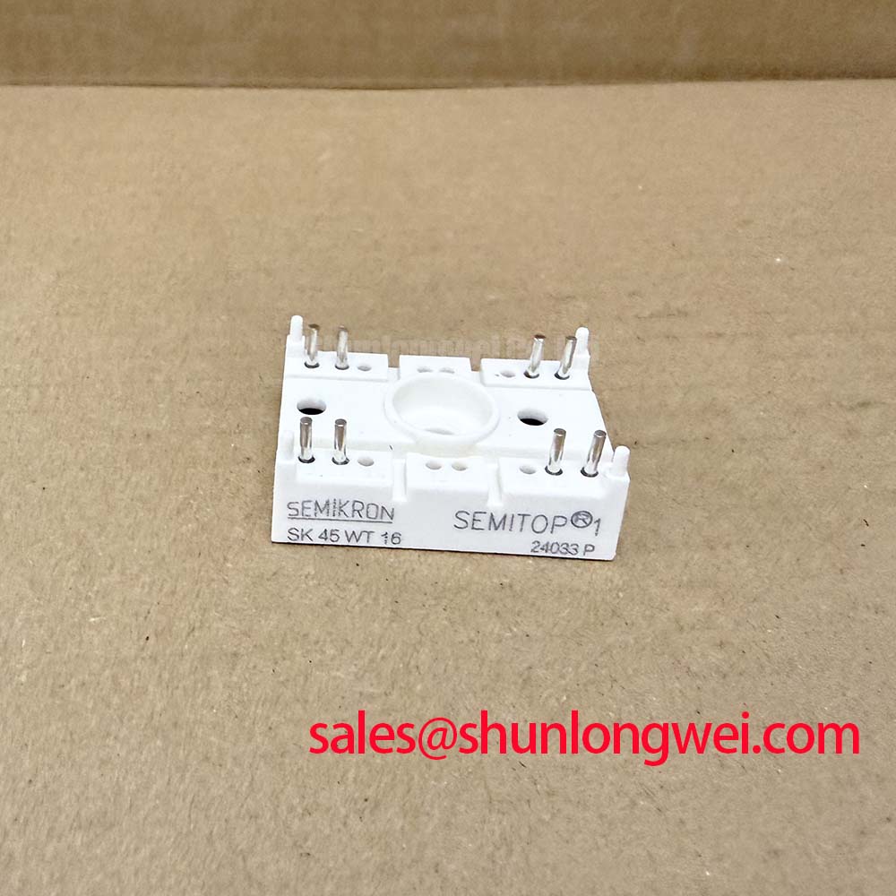
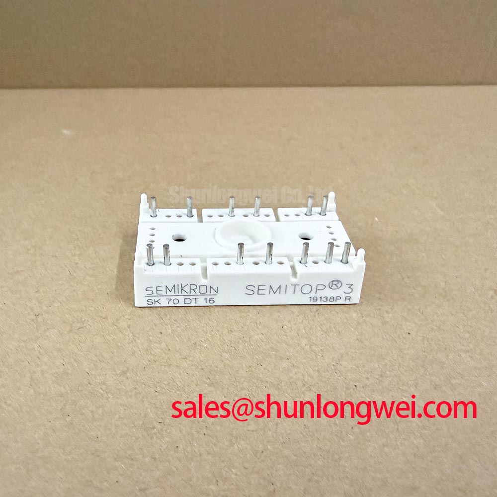
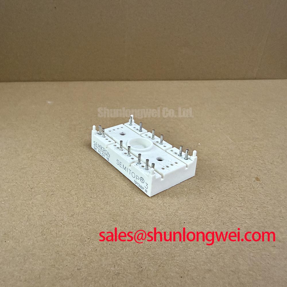
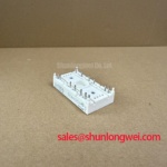
SK70DT16 Semikron 1600V 68A Thyristor Module
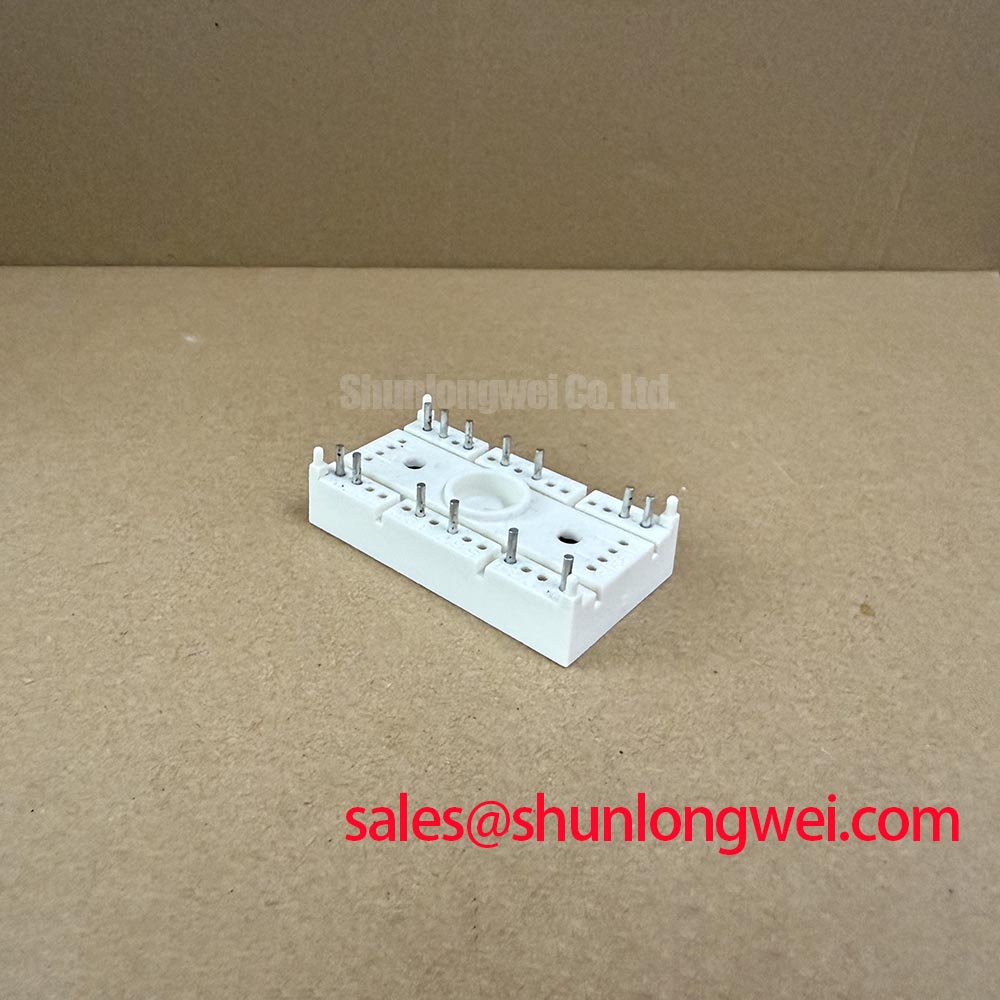
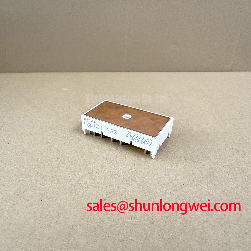
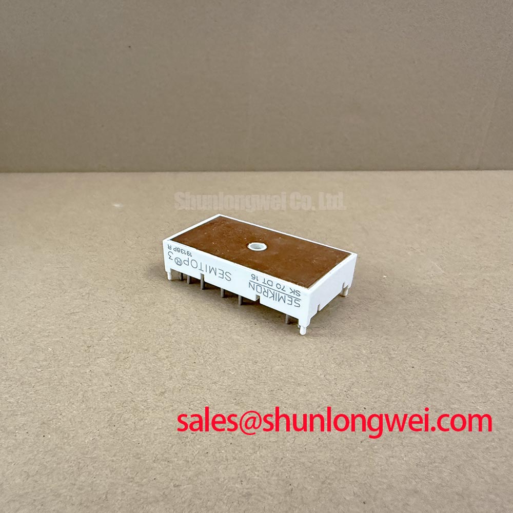
Start field evaluation with the equipment isolated, then inspect the SK70DT16 Semitrans housing, terminal condition, mounting surface, and nameplate before applying any test voltage. The provided manufacturer data identifies this Semikron power module with an official rated voltage of 1600.0 V, an official rated current of 68.0 A, and a Semitrans package. These ratings define the component identity, but they do not replace verification of the original circuit topology, commutation conditions, cooling arrangement, or gate-trigger requirements.
For a failed industrial inverter welder or medium-frequency induction heating power supply, remove the module only after the DC link has been discharged according to the equipment service procedure. Check the surrounding busbar insulation, snubber network, gate-trigger or control wiring, heatsink contact area, and signs of localized thermal stress. A cold resistance comparison between equivalent power paths can help identify an abnormal short or open condition, but a multimeter result alone cannot validate dynamic blocking capability or commutation performance.
SK70DT16 Operational Boundaries: Evaluating DC-Bus Operating Voltage Headroom Derating Limits
The 1600.0 V official voltage rating is the primary electrical boundary for the SK70DT16. During an equipment assessment, compare the measured DC-link voltage and commutation overshoot with the module’s documented rating rather than relying only on the nominal bus value. Turn-off or commutation inductance, circuit behavior, snubber condition, wiring geometry, and load regeneration can raise the instantaneous semiconductor stress above the steady bus voltage.
Altitude and terrestrial radiation effects require source-based reliability analysis. No verified FIT, Single Event Burnout, neutron-flux limit, or altitude derating value is provided here for this specific module, so a numerical SEB prediction would not be technically defensible. As a Design Consideration, engineers evaluating equipment above approximately 2000 m should obtain the applicable manufacturer qualification data and assess insulation coordination, cooling performance, creepage, clearance, and transient voltage together. The relevant system evidence should come from the equipment design authority, module documentation, or an applicable reliability study.
In the field, capture the DC bus during the actual commutation event with an appropriately rated differential probe and a measurement arrangement that does not add an unsafe loop. Inspect the physical commutation path for unnecessary conductor length and loose joints. Minimize parasitic inductance where commutation overshoot is a concern, then verify the resulting peak voltage against the module rating under the real load current and operating sequence. The Industrial Applications reference can support broader application review, while the Semikron-Danfoss Power Electronics and Modules Official Hub should be consulted for manufacturer-level product information.
When the failed unit is being replaced, compare terminal arrangement, circuit function, isolation requirements, mechanical envelope, and control characteristics before ordering a related device. The SKM75GB07E3 may be reviewed as a separate compatible-device candidate only after the system engineer confirms electrical and mechanical suitability; it should not be treated as an automatic substitute for the SK70DT16.
SK70DT16 Circuit Protection & Reliability: Calibrating Dynamic Power Loss Dissipation and Multi-R
For pulsed welding or induction-heating service, thermal assessment must follow the real current waveform rather than the average output rating alone. The official 68.0 A current value identifies the product, but the permissible operating point depends on case temperature, cooling interface, duty cycle, pulse duration, commutation behavior, and the complete manufacturer thermal specification. A transient thermal model can be useful when its resistance and time-constant data are taken from the relevant datasheet or validated test data.
As an Engineering Recommendation, separate conduction loss, commutation loss, and overload energy during the assessment. Use the measured current and voltage waveforms to determine where energy is dissipated, then compare the calculated junction temperature with the source document’s permitted limit. If the required transient thermal impedance curve is unavailable, do not replace it with a guessed multi-RC network. Instead, treat the result as provisional and validate the module with controlled thermal measurements and the original cooling assembly.
High-speed semiconductor fuse coordination also requires more than matching a nominal current. Review the fuse clearing characteristic, let-through energy, prospective fault current, bus inductance, and the module’s surge capability under the actual circuit conditions. The fuse should interrupt destructive fault energy rapidly enough to protect the power path, while nuisance operation must be assessed against the equipment’s normal pulse profile. The original protection documentation remains the authority for I²t coordination and surge limits.
Inspect the heatsink flatness, mounting pressure, thermal interface condition, and clamping hardware during replacement. Field Alert: isolate and discharge the DC link before touching the module or its control wiring, and follow the equipment manufacturer’s specified mounting procedure rather than applying an assumed torque value. If the heatsink shows distortion or the interface compound has been displaced, correcting the mechanical fault is part of the repair; fitting another module without resolving it may produce the same thermal symptom.
SK70DT16 Transient Dynamics & Electrical Design: Multi-Module Parallel Current Sharing
Parallel thyristor modules require symmetrical electrical and mechanical conditions, matched devices, and appropriate current-balancing measures. Current sharing depends on the device characteristics, trigger timing, thermal conditions, and circuit impedance, so it must be confirmed from the applicable device data and measured at the intended current and temperature. It should not be assumed solely from the product family name or package style.
Dynamic sharing is strongly affected by gate-trigger loop impedance, trigger-return geometry, busbar symmetry, stray inductance, and trigger timing. Keep the high-current paths physically balanced and route control returns according to the verified circuit topology. The system designer should determine gate-trigger current and voltage, pulse width, isolation method, commutation interval, and overcurrent protection from the actual driver and application documentation. These values are not available in the provided SK70DT16 parameter set and should not be invented.
For a repair bench check, compare the commutation waveforms of each parallel branch with the same probe arrangement and reference point. Look for unequal turn-on delay, different voltage overshoot, abnormal ringing, or current concentration in one branch. Such observations may indicate layout imbalance, trigger mismatch, thermal inequality, or a damaged surrounding component; they do not establish a single root cause without circuit comparison and controlled testing.
Where the power stage includes a front-end rectifier or complementary conversion stage, evaluate the complete topology rather than replacing only the visibly damaged device. The SKM100GB063D can be reviewed as a separate associated power-stage device, subject to confirmation of its function, voltage class, current requirement, gate-drive arrangement, and mechanical compatibility. For manufacturer background on module families and integration practices, consult the Semikron MiniSKiiP Power Modules information page.
SK70DT16 Thermal-Electrical Optimization: Long Motor Lead Reflected Wave Voltage Practical Tuning
Long motor leads can create transmission-line effects in power-converter equipment. A mismatch between cable impedance, motor input impedance, and commutation-edge behavior may produce reflected-wave voltage at the motor terminals and additional stress at the module output. The commonly cited possibility of a terminal spike approaching twice the local DC voltage is a system-level condition, not an official SK70DT16 parameter, and its actual value must be measured on the installed equipment.
When an industrial inverter welder or induction-heating power unit uses extended output wiring, inspect cable routing, shield termination, motor or transformer input characteristics, and the location of any output reactor or dv/dt filter. The correct filter or choke selection depends on operating frequency, waveform, cable length, load impedance, allowable leakage current, thermal duty, and the measured waveform. Designers should minimize ringing and verify peak voltage, common-mode current, and thermal behavior during commissioning rather than selecting a filter from voltage rating alone.
During troubleshooting, use a probe and connection method suitable for fast high-voltage commutation. Compare measurements at the module output and at the remote load, because a clean waveform at the power stage does not prove that the remote terminals are within their insulation and voltage limits. Check the snubber and clamp components for altered value, cracked bodies, loose terminals, or excessive heating. If the equipment repeatedly damages the same power position, review the commutation waveform, trigger timing, protection response, cooling condition, and load-side reflection together.
The SK70DT16 should therefore be evaluated as part of the complete power conversion assembly. Its official identity remains 1600.0 V, 68.0 A, and Semitrans package construction, while final suitability depends on the verified topology, gate-trigger or control interface, thermal path, protection coordination, and measured transient performance of the target equipment.