


Content last revised on September 28, 2026
Assembly Integrity & Layout Architecture: Implementing Thermal Margins during High-Current Operation for SKD110/12
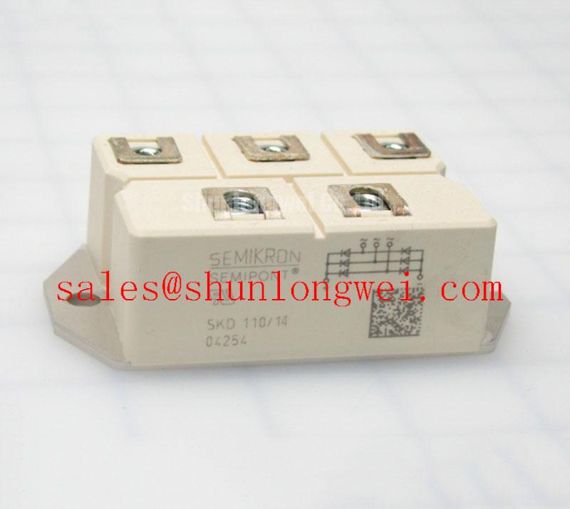
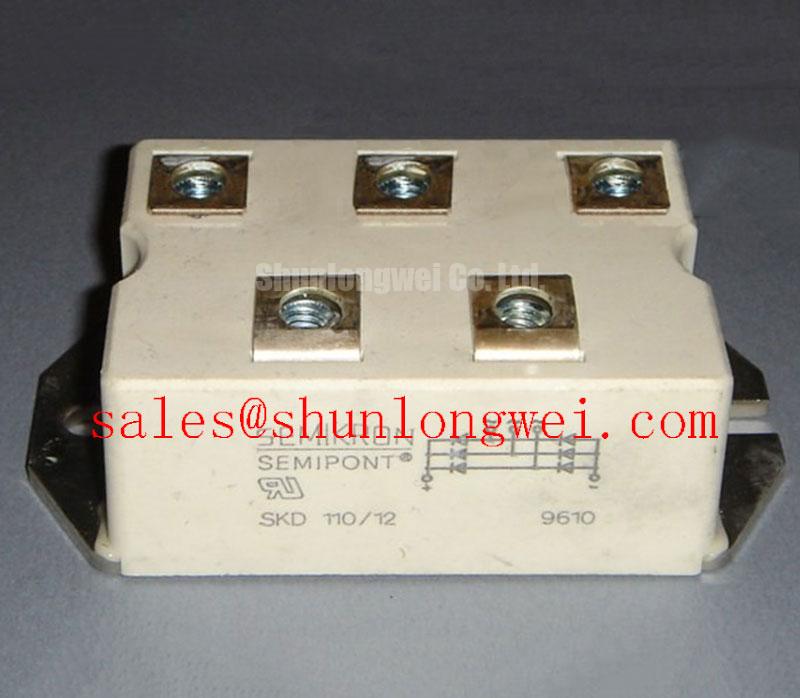
Verify the nameplate rating, inspect the Semipont housing, and check the power terminals for mechanical damage before installing SKD110/12 in a service replacement or prototype assembly. The supplied factory data identifies this Semikron bridge rectifier module with a specified voltage rating of 1200 V, a rated current of 110 A, and a Semipont package.
For a grid-tied Static Var Compensator or thyristor-switched capacitor cabinet, the first engineering task is to confirm that the replacement device matches the original electrical position, polarity, terminal arrangement, and cooling interface. The available factory parameter set confirms the 1200 V voltage rating and 110 A rated current of SKD110/12. It does not provide an ITSM surge current value, junction temperature limit, fuse I2t coordination value, or mounting torque. Those values should be taken from the applicable Semikron datasheet or installation document before a high-peak-current assessment is approved.
During inspection, check the heat transfer surface for contamination, scoring, oxidation, or uneven contact. A clean and flat interface supports consistent thermal transfer, but the appropriate thermal interface material and application method remain system and manufacturer documentation matters. The heatsink should be checked for airflow blockage and accumulated dust, especially where capacitor switching produces repeated current pulses. Thermal measurements under the actual cabinet duty cycle are more useful than relying only on a cold resistance check.
Terminal connections require the same care as the cooling path. Confirm conductor size, lug alignment, insulation clearance, and polarity against the original circuit drawing. Do not infer a permissible tightening torque from the current rating. Use the Semikron mechanical specification for this exact package and terminal arrangement. The fuse coordination table should also be reviewed with the prospective fault current and the actual semiconductor fuse characteristics rather than selected from current rating alone.
Maintenance Note: Inspect the heatsink air path and recheck contact temperature during scheduled service so dust accumulation or ageing thermal material is identified before abnormal heating develops.
Semikron’s official power electronics hub is a useful reference point for product family documentation, while the published Semikron MiniSKiiP® power module information should not be treated as a substitute for the SKD110/12 documentation.
Transient Dynamics & Electrical Design: High di/dt Commutation and Pulse-Load Behavior on SKD110/12
Before applying the module, identify whether the SKD110/12 position is used as a bridge rectifier path or as part of a larger controlled thyristor assembly. The SKD110/12 itself is a bridge rectifier module and confirms its voltage, current, and Semipont package ratings; it does not provide gate trigger current, gate trigger voltage, gate pulse rise time, holding current, latching current, or an approved pulse-train profile. These parameters are not applicable to the diode bridge and must not be assumed from the 110 A rating.
For a rectifier used in an SVC or capacitor-switching installation, the AC and DC wiring should be evaluated with the complete harness and load connected. A clean voltage waveform at the source can become distorted by cable inductance, common return impedance, connector resistance, or unsuitable isolation components. Designers should minimize the high-current commutation loop area and keep high-current conductors physically separate from sensitive measurement wiring. The final voltage and current waveforms should be verified with an appropriately rated, isolated measurement setup against the component documentation.
Repeated pulse-load operation can expose problems that are not visible during a single test. Review commutation behavior, waveform distortion, and synchronization with the AC waveform under the real cabinet load. If an oscilloscope shows ringing, unexpected current spikes, or excessive voltage overshoot, inspect the source impedance, return path, cable routing, snubber, and termination before attributing the condition to the semiconductor. Any observed transient should be evaluated against the bridge rectifier’s documented voltage and surge limits.
Any proposed snubber or MOV arrangement should be validated against the actual commutation voltage, energy, repetition rate, and cabinet earthing arrangement. SKD110/12 factory information supplied here does not state an internal protection structure or a guaranteed transient immunity level, so system qualification remains necessary.
Assembly Integrity & Layout Architecture: Implementing AC to DC Transfer Characteristics across V for SKD110/12
When SKD110/12 is evaluated in an SVC branch, the AC-to-DC behavior is determined by the complete topology, switching sequence, line impedance, load, and control angle. The product information supplied for this page confirms the module’s 1200 V voltage rating, 110 A current rating, and Semipont housing, but it does not define a firing-angle operating range, forward-voltage characteristic, reverse-recovery behavior, power-factor curve, or reactive-power limit.
Engineers should therefore begin with the original circuit diagram and identify whether the module is used in a passive rectifier position, a controlled converter leg containing separate thyristors, or a replacement location within a larger thyristor-switched capacitor assembly. Measure the line voltage, branch current, phase relationship, and switching waveform at the intended operating point. Changes in firing angle can alter conduction duration and reactive current demand in the controlled portion of the system, but the resulting operating envelope must be calculated from the actual SVC topology rather than assigned to the module alone.
Layout review should include the AC terminals, DC link or capacitor connection, snubber placement, MOV location, and protective earth path. Keep the high-current loop compact to reduce parasitic inductive overshoot, while ensuring that creepage, clearance, insulation coordination, and enclosure conditions satisfy the equipment standard selected by the system owner. The module itself should not be described as independently certified for complete equipment EMC compliance.
For a neutral comparison within the same general supplier family, engineers may review SKD82/18 as a separate product listing. It should not be treated as a drop-in replacement without checking voltage, current, mechanical fit, terminal mapping, thermal requirements, and the original equipment documentation.
SKD110/12 Circuit Protection & Reliability: Calibrating Semiconductor Protection Fuse Selection
Protection review should start by recording the prospective short-circuit current, supply impedance, fuse-clearing characteristic, conductor arrangement, and the module’s documented surge-withstand data. The available factory parameter set for SKD110/12 gives the voltage rating as 1200 V and rated current as 110 A, but it does not include the semiconductor fuse I2t value, ITSM, peak forward voltage, reverse-recovery data, or a zero-damage guarantee during a dead short.
A suitable semiconductor fuse is selected by comparing its let-through energy and clearing behavior with the device withstand limits published for the exact module revision. The comparison must include pre-arcing and total-clearing I2t, peak let-through current, system voltage, fault duration, and the available enclosure fault containment. A fuse with a matching nominal current is not automatically coordinated with a power semiconductor.
After a protection event, isolate the equipment and inspect the module, fuse holder, busbar joints, insulation, and surrounding capacitor circuit before re-energizing. Check for discolored terminals, loosened hardware, damaged insulation, and changes in the cooling interface. Do not use a continuity reading alone to approve the module; compare the measured circuit behavior with a known-good assembly and follow the manufacturer’s resistance and insulation test procedure where available.
For procurement records, identify the complete marking, package style, electrical position, and required documentation alongside the model number. The distributor product reference for Semikron SKD110/12 is available at the SKD110/12 product page. Final suitability for a grid-tied SVC or thyristor-switched capacitor system depends on verified circuit ratings, thermal installation, control architecture, and documented protection coordination.