




Content last revised on September 21, 2026
SKIIP 03NAC126V1 Circuit Protection & Reliability: Calibrating Transient Thermal Impedance
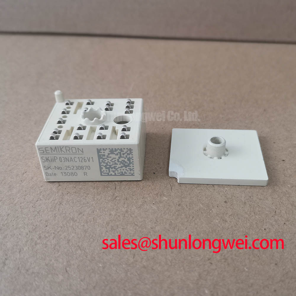
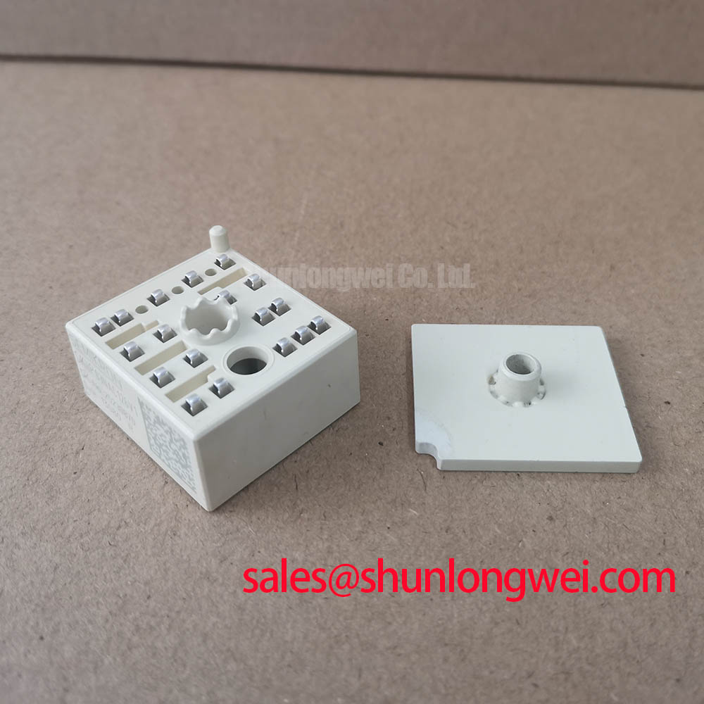
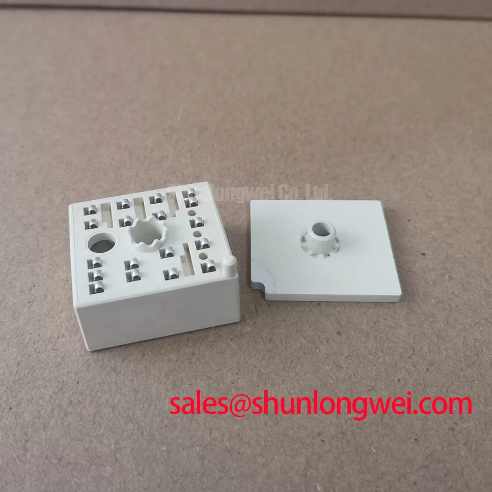
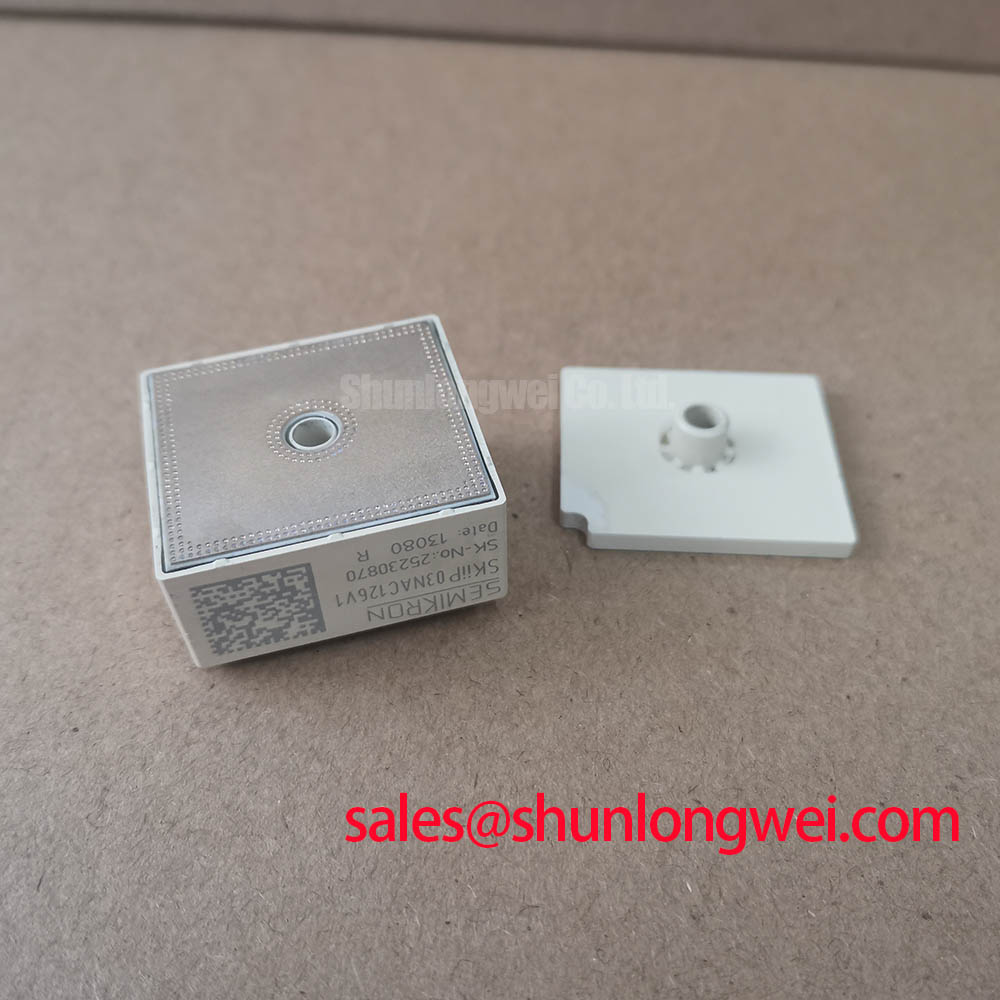
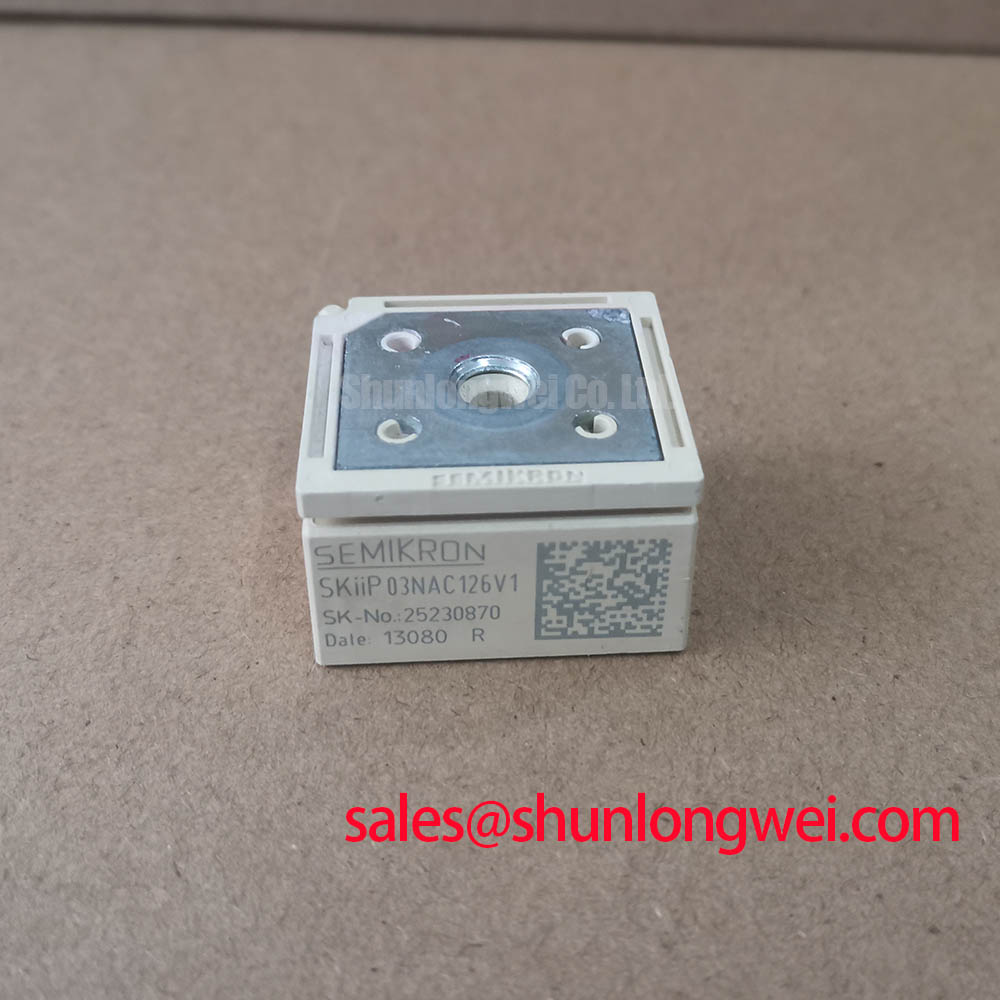
With the drive isolated and the DC link discharged, first verify that the installed unit marking matches SKIIP 03NAC126V1 and that the surrounding circuit was designed within its 1200 V and 3 A official ratings. This Semikron device uses the MiniSKiiP / SKiiP housing format. Before replacing a failed assembly, inspect connector seating, busbar contact surfaces, heatsink flatness, and signs of local heat exposure around the power path. Cold resistance measurements can identify an obvious power-path short, but they cannot validate dynamic switching behavior or protection timing.
| Parameter | Value | Classification |
|---|---|---|
| Product model | SKIIP 03NAC126V1 | Official Specification |
| Manufacturer | Semikron | Official Specification |
| Rated voltage | 1200 V | Official Specification |
| Rated current | 3 A | Official Specification |
| Housing | MiniSKiiP / SKiiP | Official Specification |
Thermal evaluation should begin with the actual load pulse, switching frequency, heatsink condition, and ambient environment rather than with a steady-state current assumption alone. The 3 A rating is an Official Specification, while allowable junction-temperature margin during pulsed operation must be established from the applicable manufacturer thermal data and the complete converter operating condition. A multi-RC transient thermal model is useful because short power pulses do not propagate through the package and heatsink in the same way as continuous dissipation.
As a Design Consideration, engineers should correlate calculated junction response with measured case or heatsink temperature and then verify the result under representative duty cycles. Uneven mounting pressure, contamination at the thermal interface, or a distorted heatsink can increase thermal resistance and change the observed margin. Where the original circuit contains bootstrap circuitry, verify that the bootstrap capacitor recharge path and diode recovery behavior remain adequate across the intended switching sequence; this is determined by the gate-driver architecture, not by the stated module ratings.
Pro Tip: Keep paired DC-link conductors physically close and symmetrical so turn-off current does not create avoidable inductive overshoot, then confirm peak voltage margin with double-pulse measurements.
Benchtop Waveform Tuning: Mitigating Stress via Overvoltage Trip Prevention During Fast Switching on SKIIP 03NAC126V1
On a bench evaluation, capture collector-emitter voltage, gate-emitter voltage, phase current, and DC-link behavior together before changing gate damping or protection thresholds. Ringing at a switching edge can arise from busbar geometry, probe placement, gate-loop inductance, or the interaction of the external drive circuit with the power stage. It should not be attributed to the SKIIP 03NAC126V1 without measurement against a known-good signal path.
For servo drives undergoing deceleration, the braking transistor and ballast resistor are system-level functions that must absorb returned mechanical energy without raising the DC link beyond the validated limit. Their selection requires the motor inertia, speed profile, commanded deceleration, DC-link capacitance, and braking control behavior. This is an Engineering Recommendation: designers should validate braking energy and resistor pulse capability in the completed drive rather than infer either from the module's 1200 V rating.
High-speed semiconductor fuse coordination also requires the actual fault-current path and the device protection limits defined in the relevant documentation. Compare the fuse clearing characteristic and its I2t behavior with the converter's expected fault event, while recognizing that cable impedance, capacitor location, and controller response alter the available fault energy. For related power-stage evaluation, SKM100GB063D can be reviewed as a separate complementary power-semiconductor reference; electrical topology, package interface, drive requirements, and ratings must be checked independently.
SKIIP 03NAC126V1 Circuit Protection & Reliability: Calibrating High-Speed Fault Management Through VCE Desaturation
Desaturation monitoring is implemented by the gate-driver system, not confirmed by the basic published voltage, current, and housing data for this unit. When a drive uses desaturation sensing, the system integrator should verify blanking behavior, sensing-path integrity, fault propagation, and controlled turn-off response against the original drive documentation. A rapid current rise or abnormal collector-emitter voltage may indicate a fault condition, but waveform capture is required before assigning a single cause.
Soft turn-off is commonly considered where an abrupt interruption of inductive current could elevate voltage stress. As a Design Consideration, minimize the commutation-loop and gate-loop parasitic inductance to suppress turn-off overshoot, then verify measured peaks against the DC-link voltage and validated device limits during switching tests. Maintain suitable physical clearance around high-energy conductors and avoid routing low-level desaturation or gate-sense traces beside noisy power paths.
For MiniSKiiP platform context, consult the manufacturer’s Semikron MiniSKiiP Power Modules information alongside the documentation for the original equipment. A replacement assessment should confirm connector assignment, control-board compatibility, cooling interface, and protection implementation before energizing the converter.
SKIIP 03NAC126V1 Operational Boundaries: Evaluating Thermal Feedback Limits
Static current sharing in parallel power paths can be influenced by the positive temperature coefficient of VCE(sat), but stable dynamic sharing also depends on matched gate-loop wiring, commutation geometry, switching timing, and thermal coupling. This is a Design Consideration rather than an Official Specification for SKIIP 03NAC126V1. Do not assume that similar physical placement alone establishes balanced switching stress.
For high-dynamics multi-axis CNC and robotics servo equipment, this part can be evaluated only where the original electrical ratings, mechanical interface, and control topology correspond to the installed design. When reviewing an alternative within the same product family, SKIIP37AC12T4V1 should be compared using documented voltage, current, topology, interface, thermal, and driver requirements rather than treated as a direct replacement. Broader selection and system-reliability practices are available in the Power Electronics Masterclass.